Refer to the Mainline Reverse Loop Schematic.
This program utilizes the Basic Stamp II microcontroller which has 16 I/O bit positions. External addressable input multiplexers (74HC151) and an output gate array (74154) are used for interfacing the turnouts and sensor/button inputs. Two output bit positions are assigned to control each turnout. A single bit controls each of the track power polarity relays via a 8 bit addressable latch (74HC259 and ULN2803). Each block detector, optical sensor, turnout sensor, and control button is assigned an input bit position.
Basic Stamp I/O bit p6 is connected to a speaker and used to sound warning tones. Basic Stamp I/O bit p5 is connected to a Led and used to indicate operation (heartbeat). Flashing indicates that the code is cycling in the main program loop. Basic Stamp I/O bit p7 is connected to an on/off switch. When on (0), normal operation mode is enabled. When off (1), manual mode is enabled.
Basic Stamp I/O bits p3 through p0 are used for addressing the 74154, 74HC75, and 74HC151's. Basic Stamp I/O bits p14 through p8 are used to drive the chip enable bits. In this way, the operating program is in control of setup and settle times for the various inputs and outputs. The 74HC151 output pins are or'd using 74HC32 gates to Basic Stamp I/O bit p4 for input to the operating program.
Switch machine operational power requires that a driver circuit be used for each coil. Each 74154 output is connected to the base circuit of a TIP127 five amp Darlington transistor. When a turnout is to be positioned, the Basic Stamp program pulses the appropriate 74154 output for a nominal 200 ms. This causes the driver circuit to energize the switch machine coil.
One area of risk in the present design involves the p8 I/O bit that controls the enable inputs of the 74154. A low on p8 causes the switch machine coil addressed by I/O bits p3 through p0 to be powered. The switch machine coil will be heat damaged if the p8 I/O bit is low too long; greater than 2 seconds. Various coding safeguards are in place to minimize this possibility.
The power polarity relays and hidden track train position indicators are driven using a ULN2803 driver. This IC contains 8 independent NPN open collector driver circuits capable of 500 mA each. These circuits include back EMF protection diodes. Five volt relays are used to control the reverse loop track power polarity. When energized, these relays draw approximately 200 mA of current.
Each train detection sensor consists of an infrared emitter/detector pair positioned on each side of the track. A train passing between them breaks the infrared light beam. The detector side is connected to a multiplexer input pin. Under normal conditions, the addressed input bit will be low. The input bit will be high whenever the infrared light beam is blocked. The 100 ohm value of the resistor in series with the infrared emitter results in about 4 inches of working distance using the emitter/detector pair shown. The resistor value can be lowered to increase the working distance between the emitter and detector. Use care not to exceed the continuous forward current limit of the emitter diode.
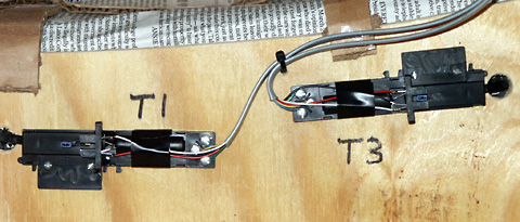
The turnout position sensor is a modular infrared emitter/detector positioned such that an open turnout breaks the light beam. The switch machine manual positioning pin is used for this; a small plastic jumper (blue) has been carefully glued to the switch machine. In the normal or 'straight' position, the input state is low. In the 'open' position, the input state is high.
The current design will not support Tortoise switch machines without some major modifications to both hardware and software. Perhaps a future design enhancement.