Refer to the Turntable Schematic.
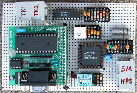
The turntable control circuit uses the 74C922 keypad encoder to interface and debounce the push button key input. The capacitors associated with the osc and msk inputs determine the key scan rate and debounce time period; 600 hz and 10 msec respectively.
The stepper motor is a 12 volt unit with a 3.6 degree step angle. The stepper motor is driven by an Allegro 3977 stepper motor controller which provide a simplified interface to the BS2 and the ability to microstep the motor. Micro stepping is used to provide the necessary accuracy for turntable bridge track rail alignment.
A 74LS38 quad open collector NAND gate is used to drive the switch machine coils for the approach track turnouts. Each turnout control bit is connected to the base circuit of a TIP127 darlington transistor. When a turnout is to be positioned, this program selects the appropriate NAND gate and pulses the common NAND gate inputs for a nominal 250 ms. This causes the TIP127 driver circuit to energize the turnout coil.
An input pin of the Basic Stamp is connected to a position sensor that is used to identify the turntable bridge rotation reference point. If continuous 360 degree rotation of the turntable bridge occurs, a sensor circuit problem is the likely cause.
An output pin of the Basic Stamp is connected to a Led and used to indicate the status of operator keypad input.
An input pin of the Basic Stamp is connected to a switch and used to select normal or test mode program operation. When off (1), normal turntable functions as described herein are enabled. When on (0), test mode is enabled. In test mode, the turntable bridge will be stepped from its current position approximately 60 degrees clockwise. It is then stepped 60 degrees counter-clockwise. This sequence will be repeated as long as test mode is enabled. If the home sensor position is crossed during either motion, a short chirp tone will be sounded. Also during test mode, pressing a keypad button will result in key number of tones being sounded with 0 = 10, * = 11, and # = 12 tones respectively.
The normal/test mode pin is also connected to a led that serves as a heartbeat indicator.
An output pin of the Basic Stamp is connected to a speaker and used to sound warning or input error tones.
Update 1-17-2012. The components associated with the PDF pin of the Allegro 3977 stepper motor controller effect the operating frequency of the internal PWM circuit. The variable resistor is normally set to provide maximum resistance of 5k ohms. Depending on other component tolerances, this might result in a audible high frequency sound, kind of like a repeating squeak or bird chirp, while the turntable is stepping. A slight adjustment of this variable resistor can be used to increase the operating frequency of the PWM circuit above the human hearing threshold. This can easily be done by commanding a move operation and adjusting until the sound is just no longer heard.