|
Grade Crossing Program Code |
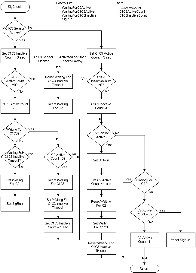
This page contains the source code portion of the Basic Stamp 2 program that controls the grade crossings. The version 2 code improves the train detection logic and Led lamp simulation effect. The code has also been converted to PBASIC 2.5 to make the logic easier to understand. See a flow chart that details the train detection logic.
The complete code and documentation can be downloaded using this link: GradeCrossingV2.zip. The older code can be downloaded using this link: GradeCrossingV1.zip
' ====================================================================== ' GradeCrossingV2.bs2 4-14-2005 '{$PBASIC 2.5} '{$STAMP BS2} ' I/O bit definitions. Sig1Lamp1 CON 0 ' BS2 bit 0 Sig1Lamp2 CON 1 ' BS2 bit 1 Sig1C1C3 VAR IN2 ' BS2 bit 2 Sig1C2 VAR IN3 ' BS2 bit 3 Sig1Snd1 CON 4 ' BS2 bit 4 Sig1Snd2 CON 5 ' BS2 bit 5 Sig1Servo CON 6 ' BS2 bit 6 LedPin CON 7 ' BS2 bit 7 RunMode VAR IN7 ' BS2 bit 7 Sig2Lamp1 CON 8 ' BS2 bit 8 Sig2Lamp2 CON 9 ' BS2 bit 9 Sig2C1C3 VAR IN10 ' BS2 bit 10 Sig2C2 VAR IN11 ' BS2 bit 11 Sig2Snd1 CON 12 ' BS2 bit 12 Sig2Snd2 CON 13 ' BS2 bit 13 Sig2Servo CON 14 ' BS2 bit 14 SoundSel VAR IN15 ' BS2 bit 15 ' Other program constants DefaultDir CON %0111001101110011 OneSecond CON 40 ThreeSecond CON 120 SigFlash CON 20 LampSimStep CON 3 ' Lamp simulator change steps ' General control variables. LedCount VAR Byte ' Countdown for Led state toggle ' Signal #1 working variables and constants. Sig1C1C3Act VAR Byte ' C1/C3 retriggerable active timeout Sig1C1C3Inact VAR Byte ' C1/C3 retriggerable inactive timeout Sig1C2Act VAR Byte ' C2 retriggerable active timeout Sig1Ctrl VAR Byte ' Signal 1 control bits Sig1Run VAR Sig1Ctrl.BIT0 ' 0 = stop, 1 = run Sig1WaitC2 VAR Sig1Ctrl.BIT1 ' 1 = Waiting for C2 active Sig1WaitC1C3a VAR Sig1Ctrl.BIT2 ' 1 = Waiting for C1/C3 active Sig1WaitC1C3i VAR Sig1Ctrl.BIT3 ' 1 = Waiting for C1/C3 In-ctive Sig1Gate VAR Sig1Ctrl.BIT4 ' 0 = Gate up, 1 = Gate down Sig1GateDelay VAR Byte ' End of train raise gate delay Sig1Flash VAR Byte ' Lamp change rate LampSim1 VAR Nib ' Counter for lamp simulator Gate1Pos VAR Byte ' Servo position pulse width Gate1Up CON 10 ' Gate up position Gate1Dn CON 210 ' Gate down position Gate1Rate CON 3 ' Gate speed - minimum value of 1 ' Signal #2 working variables and constants. Sig2C1C3Act VAR Byte ' C1/C3 retriggerable active timeout Sig2C1C3Inact VAR Byte ' C1/C3 retriggerable inactive timeout Sig2C2Act VAR Byte ' C2 retriggerable active timeout Sig2Ctrl VAR Byte ' Signal 2 control bits Sig2Run VAR Sig2Ctrl.BIT0 ' 0 = stop, 1 = run Sig2WaitC2 VAR Sig2Ctrl.BIT1 ' 1 = Waiting for C2 active Sig2WaitC1C3a VAR Sig2Ctrl.BIT2 ' 1 = Waiting for C1/C3 active Sig2WaitC1C3i VAR Sig2Ctrl.BIT3 ' 1 = Waiting for C1/C3 In-ctive Sig2Gate VAR Sig2Ctrl.BIT4 ' 0 = Gate up, 1 = Gate down Sig2GateDelay VAR Byte ' End of train raise gate delay Sig2Flash VAR Byte ' Lamp change rate LampSim2 VAR Nib ' Counter for lamp simulator Gate2Pos VAR Byte ' Servo position pulse width Gate2Up CON 10 ' Gate up position Gate2Dn CON 210 ' Gate down position Gate2Rate CON 3 ' Gate speed - minimum value of 1 '-------------------------------------------------------------------------- ' This section initializes all working variables to power on settings. ProgramStart: DIRS = DefaultDir ' Set default I/O direction bits Sig1Ctrl = 0 ' Clear signal 1 control bits Sig1Flash = 0 ' Clear signal 1 lamp change rate Sig2Ctrl = 0 ' Clear signal 2 control bits Sig2Flash = 0 ' Clear signal 2 lamp change rate '-------------------------------------------------------------------------- ' Main program loop. Call each signals processing routine. The pause command ' value should be adjusted if necessary to achieve the 3 second delay period. ' The SigFlash value may need slight adjustment to achieve the desired proto ' typical flash rate. ' ' The RunMode I/O pin serves a dual purpose with the program heartbeat led. ' The pin is set to input to read the mode switch position. The pin is then ' made an output to drive the heartbeat led. MainLoop: INPUT LedPin ' Set LedPin direction to input IF RunMode = 0 THEN TestLoop ' Jump if test mode selected OUTPUT LedPin ' Set LedPin direction to output GOSUB Sig1Check ' Check signal 1 inputs GOSUB Sig1Proc ' Process signal 1 flash GOSUB MoveGate1 ' Move signal 1 gates GOSUB Sig2Check ' Check signal 2 inputs GOSUB Sig2Proc ' Process signal 2 flash GOSUB MoveGate2 ' Move signal 2 gates IF LedCount = 0 THEN ' Heartbeat indicator change? LedCount = OneSecond / 2 TOGGLE LedPin ' Change Led state ELSE LedCount = LedCount - 1 ' Decrement heartbeat Led counter ENDIF PAUSE 10 ' Adjusts loop rate for delays. It GOTO MainLoop ' also effects the gate speed. '-------------------------------------------------------------------------- ' Signal 1 sensor input and timer processing. Sig1Check: IF Sig1C1C3 = 1 THEN ' C1/C3 sensor active? Sig1C1C3Inact = ThreeSecond ' Yes, set C1/C3 in-active timer IF Sig1C1C3Act = 0 THEN ' Train blocking C1/C3 sensor? Sig1WaitC2 = 0 ' Yes, reset waiting for C2 active Sig1WaitC1C3i = 0 ' Reset waiting for C1/C3 in-active ELSE Sig1C1C3Act = Sig1C1C3Act - 1 ' Decrement the active timer IF Sig1WaitC1C3a = 1 OR Sig1WaitC1C3i = 1 THEN IF Sig1C2Act = 0 THEN ' C2 timer expired? Sig1WaitC1C3a = 0 ' Yes, reset waiting for C1/C3 active Sig1WaitC1C3i = 1 ' Reset waiting for C1/C3 in-active Sig1C1C3Inact = OneSecond ' Set C1/C3 in-active timer ENDIF ELSE Sig1WaitC2 = 1 ' Set waiting for C2 active Sig1Run = 1 ' Start signals ENDIF ENDIF ELSE Sig1C1C3Act = ThreeSecond ' In-active, set C1/C3 active timer IF Sig1C1C3Inact = 0 THEN ' Train backed away? Sig1WaitC2 = 0 ' Yes, reset waiting for C2 active Sig1WaitC1C3i = 0 ' Reset waiting for C1/C3 in-active ELSE Sig1C1C3Inact = Sig1C1C3Inact - 1 ' Decrement the in-active timer ENDIF ENDIF Sig1C2Check: IF Sig1C2 = 1 THEN ' Read C2 sensor Sig1C2Act = OneSecond ' Set C2 active timer Sig1Run = 1 ' Start signals Sig1WaitC2 = 0 ' Reset waiting for C2 active Sig1WaitC1C3a = 1 ' Set waiting for C1/C3 active Sig1WaitC1C3i = 0 ' Reset waiting for C1/C3 in-active ELSE IF Sig1WaitC2 = 0 THEN ' Not waiting for C2 active? IF Sig1C2Act = 0 THEN ' C2 timer expired? Sig1Run = 0 ' Stop signals ELSE Sig1C2Act = Sig1C2Act - 1 ' Decrement C2 counter ENDIF ENDIF ENDIF RETURN '-------------------------------------------------------------------------- ' Signal 1 flash processing. Perform functions based upon the state of the ' signal run bit. ' ' Sig1Run = 0: ' If a lamp is on, then this is first entry to routine since the ' signal run bit was reset. Extinguish lamps and clear flash counter. ' Stop sounds and raise crossing gates. ' ' Sig1Run = 1: ' If both lamps are off, then this is first entry to routine since ' the signal run bit was set. Set first lamp on and initialize flash ' counter. Start bell only sound and lower crossing gates. ' ' The Sig1C2Act counter is used by this routine for switching between sound ' 2 (BELL AND train) AND sound 1 (BELL only). Sound two is used whenever the ' C2 sensor is active. Sig1C2Act causes sound 2 to remain active until about ' 1/4 second after the end of the train. Sig1Proc: IF Sig1Run = 1 THEN ' Is Sig1Run active? IF IN0 = 0 AND IN1 = 0 THEN ' Yes, both lamps off? Sig1Gate = 1 ' Yes, lower the gate IF SoundSel <> 0 THEN ' Sound enabled? LOW Sig1Snd2 ' Yes, turn off sound 2 HIGH Sig1Snd1 ' Turn on sound 1 (bell only) ENDIF IF LedCount.BIT0 = 1 THEN ' Random starting lamp HIGH Sig1Lamp1 ' Select first lamp ELSE HIGH Sig1Lamp2 ' Select first lamp ENDIF Sig1Flash = SigFlash ' Set lamp switch delay count ENDIF ' This code in this IF section is used to simulate an incandescent signal ' lamps using an Led by gradual turn on/off each time the routine is called. ' If using signals with incandescent bulbs, adjust indicated lines of code. IF Sig1Flash = 0 THEN ' Change lamp states? TOGGLE Sig1Lamp1 ' Change to new lamp state TOGGLE Sig1Lamp2 ' Change to new lamp state IF LampSim1 = 0 THEN ' Yes, lamp change count 0? LampSim1 = LampSimStep -1 ' * Comment out if incandescent lamps ' Sig1Flash = SigFlash ' * Uncomment if incandescent lamps ENDIF ENDIF IF LampSim1 <> 0 THEN ' Lamp change done? LampSim1 = LampSim1 - 1 ' No, decrement intensity change IF LampSim1 = 0 THEN ' Lamp sim count now 0? Sig1Flash = SigFlash ' Reset lamp switch delay count ELSE PAUSE LampSim1 ' Delay TOGGLE Sig1Lamp1 ' Change to old lamp state TOGGLE Sig1Lamp2 ' Change to old lamp state ENDIF ELSE Sig1Flash = Sig1Flash - 1 ' Decrement lamp switch count ENDIF IF IN3 = 1 THEN ' Sig1C2 sensor active? Sig1GateDelay = OneSecond / 4 ' Yes, set new gate delay value IF SoundSel <> 0 THEN ' Sound enabled? LOW Sig1Snd1 ' Yes, turn off sound 1 HIGH Sig1Snd2 ' Turn on sound 2 (bell & train) ENDIF ELSE IF Sig1GateDelay <> 0 THEN ' Gate delay value set? IF Sig1GateDelay = 1 THEN ' Yes, Time delay at 1? Sig1Gate = 0 ' Yes, raise the gate IF SoundSel <> 0 THEN ' Sound enabled? LOW Sig1Snd2 ' Yes, turn off sound 2 HIGH Sig1Snd1 ' Turn on sound 1 (bell only) ENDIF ENDIF Sig1GateDelay = Sig1GateDelay - 1 ' Decrement gate delay ENDIF ENDIF ELSE Sig1Gate = 0 ' Raise the gate PAUSE Sig1Flash * 5 ' Delay LOW Sig1Lamp1 ' Turn off lamp LOW Sig1Lamp2 ' Turn off lamp LOW Sig1Snd1 ' Turn off sound 1 LOW Sig1Snd2 ' Turn off sound 2 Sig1Flash = 0 ' Clear counter LampSim1 = 0 ' Clear counter ENDIF RETURN '-------------------------------------------------------------------------- ' Move Signal 1 gate. This routine outputs a servo control pulse that is ' used to position the crossing gates. The gate position is determined by ' the Sig1Gate variable and the Gate1Pos variable. The final up/down position ' of the gate is adjusted by the constants Gate1Up and Gate1Dn. The speed ' of the gate is controlled by Gate1Rate. ' ' Some additional logic has been added to eleminate servo chatter caused by ' stiff actuating cables. The late move of the servo moves an additional ' amount past the final position and then moves back to the final position. MoveGate1: IF Sig1Gate = 0 THEN ' Up position requested? IF Gate1Pos > Gate1Up THEN ' Yes, up change required? Gate1Pos = Gate1Pos - Gate1Rate ' Yes, move gate up a bit IF Gate1Pos <= Gate1Up THEN ' Will move be done? Gate1Pos = Gate1Pos - (Gate1Rate*2) ' Add extra move amount PULSOUT Sig1Servo, 500 + (Gate1Pos*2) ' Set new gate position PAUSE 20 Gate1Pos = Gate1Pos + (Gate1Rate*2) ' Remove extra move ENDIF ENDIF ELSE IF Gate1Pos < Gate1Dn THEN ' Down change required? Gate1Pos = Gate1Pos + Gate1Rate ' Yes, move gate down a bit IF Gate1Pos => Gate1Dn THEN ' Will move be done? Gate1Pos = Gate1Pos + (Gate1Rate*2) ' Add extra move amount PULSOUT Sig1Servo, 500 + (Gate1Pos*2) ' Set new gate position PAUSE 20 Gate1Pos = Gate1Pos - (Gate1Rate*2) ' Remove extra move ENDIF ENDIF ENDIF PULSOUT Sig1Servo, 500 + (Gate1Pos*2) ' Set/refresh gate position RETURN '-------------------------------------------------------------------------- ' Signal 2 sensor input and timer processing. Sig2Check: IF Sig2C1C3 = 1 THEN ' C1/C3 sensor active? Sig2C1C3Inact = ThreeSecond ' Yes, set C1/C3 in-active timer IF Sig2C1C3Act = 0 THEN ' Train blocking C1/C3 sensor? Sig2WaitC2 = 0 ' Yes, reset waiting for C2 active Sig2WaitC1C3i = 0 ' Reset waiting for C1/C3 in-active ELSE Sig2C1C3Act = Sig2C1C3Act - 1 ' Decrement the active timer IF Sig2WaitC1C3a = 1 OR Sig2WaitC1C3i = 1 THEN IF Sig2C2Act = 0 THEN ' C2 timer expired? Sig2WaitC1C3a = 0 ' Yes, reset waiting for C1/C3 active Sig2WaitC1C3i = 1 ' Reset waiting for C1/C3 in-active Sig2C1C3Inact = OneSecond ' Set C1/C3 in-active timer ENDIF ELSE Sig2WaitC2 = 1 ' Set waiting for C2 active Sig2Run = 1 ' Start signals ENDIF ENDIF ELSE Sig2C1C3Act = ThreeSecond ' In-active, set C1/C3 active timer IF Sig2C1C3Inact = 0 THEN ' Train backed away? Sig2WaitC2 = 0 ' Yes, reset waiting for C2 active Sig2WaitC1C3i = 0 ' Reset waiting for C1/C3 in-active ELSE Sig2C1C3Inact = Sig2C1C3Inact - 1 ' Decrement the in-active timer ENDIF ENDIF Sig2C2Check: IF Sig2C2 = 1 THEN ' Read C2 sensor Sig2C2Act = OneSecond ' Set C2 active timer Sig2Run = 1 ' Start signals Sig2WaitC2 = 0 ' Reset waiting for C2 active Sig2WaitC1C3a = 1 ' Set waiting for C1/C3 active Sig2WaitC1C3i = 0 ' Reset waiting for C1/C3 in-active ELSE IF Sig2WaitC2 = 0 THEN ' Not waiting for C2 active? IF Sig2C2Act = 0 THEN ' C2 timer expired? Sig2Run = 0 ' Stop signals ELSE Sig2C2Act = Sig2C2Act - 1 ' Decrement C2 counter ENDIF ENDIF ENDIF RETURN '-------------------------------------------------------------------------- ' Signal 2 flash processing. Perform functions based upon the state of the ' signal run bit. ' ' Sig2Run = 0: ' If a lamp is on, then this is first entry to routine since the ' signal run bit was reset. Extinguish lamps and clear flash counter. ' Stop sounds and raise crossing gates. ' ' Sig2Run = 1: ' If both lamps are off, then this is first entry to routine since ' the signal run bit was set. Set first lamp on and initialize flash ' counter. Start bell only sound and lower crossing gates. ' ' The Sig2C2Act counter is used by this routine for switching between sound ' 2 (BELL AND train) AND sound 1 (BELL only). Sound two is used whenever the ' C2 sensor is active. Sig2C2Act causes sound 2 to remain active until about ' 1/4 second after the end of the train. Sig2Proc: IF Sig2Run = 1 THEN ' Is Sig2Run active? IF IN8 = 0 AND IN9 = 0 THEN ' Yes, both lamps off? Sig2Gate = 1 ' Yes, lower the gate IF SoundSel <> 0 THEN ' Sound enabled? LOW Sig2Snd2 ' Yes, turn off sound 2 HIGH Sig2Snd1 ' Turn on sound 1 (bell only) ENDIF IF LedCount.BIT0 = 1 THEN ' Random starting lamp HIGH Sig2Lamp1 ' Select first lamp ELSE HIGH Sig2Lamp2 ' Select first lamp ENDIF Sig2Flash = SigFlash ' Set lamp switch delay count ENDIF ' This code in this IF section is used to simulate an incandescent signal ' lamps using an Led by gradual turn on/off each time the routine is called. ' If using signals with incandescent bulbs, adjust indicated lines of code. IF Sig2Flash = 0 THEN ' Change lamp states? TOGGLE Sig2Lamp1 ' Change to new lamp state TOGGLE Sig2Lamp2 ' Change to new lamp state IF LampSim2 = 0 THEN ' Yes, lamp change count 0? LampSim2 = LampSimStep -1 ' * Comment out if incandescent lamps ' Sig2Flash = SigFlash ' * Uncomment if incandescent lamps ENDIF ENDIF IF LampSim2 <> 0 THEN ' Lamp change done? LampSim2 = LampSim2 - 1 ' No, decrement intensity change IF LampSim2 = 0 THEN ' Lamp sim count now 0? Sig2Flash = SigFlash ' Reset lamp switch delay count ELSE PAUSE LampSim2 ' Delay TOGGLE Sig2Lamp1 ' Change to old lamp state TOGGLE Sig2Lamp2 ' Change to old lamp state ENDIF ELSE Sig2Flash = Sig2Flash - 1 ' Decrement lamp switch count ENDIF IF IN11 = 1 THEN ' Sig2C2 sensor active? Sig2GateDelay = OneSecond / 4 ' Yes, set new gate delay value IF SoundSel <> 0 THEN ' Sound enabled? LOW Sig2Snd1 ' Yes, turn off sound 1 HIGH Sig2Snd2 ' Turn on sound 2 (bell & train) ENDIF ELSE IF Sig2GateDelay <> 0 THEN ' Gate delay value set? IF Sig2GateDelay = 1 THEN ' Yes, Time delay at 1? Sig2Gate = 0 ' Yes, raise the gate IF SoundSel <> 0 THEN ' Sound enabled? LOW Sig2Snd2 ' Yes, turn off sound 2 HIGH Sig2Snd1 ' Turn on sound 1 (bell only) ENDIF ENDIF Sig2GateDelay = Sig2GateDelay - 1 ' Decrement gate delay ENDIF ENDIF ELSE Sig2Gate = 0 ' Raise the gate PAUSE Sig2Flash * 5 ' Delay LOW Sig2Lamp1 ' Turn off lamp LOW Sig2Lamp2 ' Turn off lamp LOW Sig2Snd1 ' Turn off sound 1 LOW Sig2Snd2 ' Turn off sound 2 Sig2Flash = 0 ' Clear counter LampSim2 = 0 ' Clear counter ENDIF RETURN '-------------------------------------------------------------------------- ' Move Signal 2 gate. This routine outputs a servo control pulse that is ' used to position the crossing gates. The gate position is determined by ' the Sig1Gate variable and the Gate1Pos variable. The final up/down position ' of the gate is adjusted by the constants Gate1Up and Gate1Dn. The speed ' of the gate is controlled by Gate1Rate. ' ' Some additional logic has been added to eleminate servo chatter caused by ' stiff actuating cables. The late move of the servo moves an additional ' amount past the final position and then moves back to the final position. MoveGate2: IF Sig2Gate = 0 THEN ' Up position requested? IF Gate2Pos > Gate2Up THEN ' Yes, up change required? Gate2Pos = Gate2Pos - Gate2Rate ' Yes, move gate up a bit IF Gate2Pos <= Gate2Up THEN ' Will move be done? Gate2Pos = Gate2Pos - (Gate2Rate*2) ' Add extra move amount PULSOUT Sig2Servo, 500 + (Gate2Pos*2) ' Set new gate position PAUSE 20 Gate2Pos = Gate2Pos + (Gate2Rate*2) ' Remove extra move ENDIF ENDIF ELSE IF Gate2Pos < Gate2Dn THEN ' Down change required? Gate2Pos = Gate2Pos + Gate2Rate ' Yes, move gate down a bit IF Gate2Pos => Gate2Dn THEN ' Will move be done? Gate2Pos = Gate2Pos + (Gate2Rate*2) ' Add extra move amount PULSOUT Sig2Servo, 500 + (Gate2Pos*2) ' Set new gate position PAUSE 20 Gate2Pos = Gate2Pos - (Gate2Rate*2) ' Remove extra move ENDIF ENDIF ENDIF PULSOUT Sig2Servo, 500 + (Gate2Pos*2) ' Set/refresh gate position RETURN '-------------------------------------------------------------------------- ' Test/exercise loop. Called if RunMode is zero. Continue looping until ' RunMode is not zero. TestLoop: LOW Sig1Lamp1 ' Set signal 1 lamp 1 off FOR Sig1Flash = 1 TO 6 TOGGLE Sig1Lamp1 ' Flash signal 1 lamp 1 PAUSE 200 NEXT LOW Sig1Lamp2 ' Set signal 1 lamp 2 off FOR Sig1Flash = 1 TO 6 TOGGLE Sig1Lamp2 ' Flash signal 1 lamp 2 PAUSE 200 NEXT HIGH Sig1Snd1 ' Turn on sound 1 (bell only) Sig1Gate = 1 ' Lower signal 1 gate FOR Sig1Flash = 1 TO 70 GOSUB MoveGate1 PAUSE 15 NEXT LOW Sig1Snd1 ' Turn off sound 1 HIGH Sig1Snd2 ' Turn on sound 2 (bell & train) Sig1Gate = 0 ' Raise signal 1 gate FOR Sig1Flash = 1 TO 70 GOSUB MoveGate1 PAUSE 15 NEXT LOW Sig1Snd2 ' Turn off sound 2 Sig1Flash = 0 LOW Sig2Lamp1 ' Set signal 2 lamp 1 off FOR Sig2Flash = 1 TO 6 TOGGLE Sig2Lamp1 ' Flash signal 2 lamp 1 PAUSE 200 NEXT LOW Sig2Lamp2 ' Set signal 2 lamp 2 off FOR Sig2Flash = 1 TO 6 TOGGLE Sig2Lamp2 ' Flash signal 2 lamp 2 PAUSE 200 NEXT HIGH Sig2Snd1 ' Turn on sound 1 (bell only) Sig2Gate = 1 ' Lower signal 2 gate FOR Sig2Flash = 1 TO 70 GOSUB MoveGate2 PAUSE 15 NEXT LOW Sig2Snd1 ' Turn off sound 1 HIGH Sig2Snd2 ' Turn on sound 2 (bell & train) Sig2Gate = 0 ' Raise signal 1 gate FOR Sig2Flash = 1 TO 70 GOSUB MoveGate2 PAUSE 15 NEXT LOW Sig2Snd2 ' Turn off sound 2 Sig2Flash = 0 IF RunMode = 0 THEN TestLoop GOTO ProgramStart
Navigation: Grade Crossing D&B Home Buczynski.com Index
Copyright © 2006 Don Buczynski
San Diego, California