|
Grade Crossing Program Description |
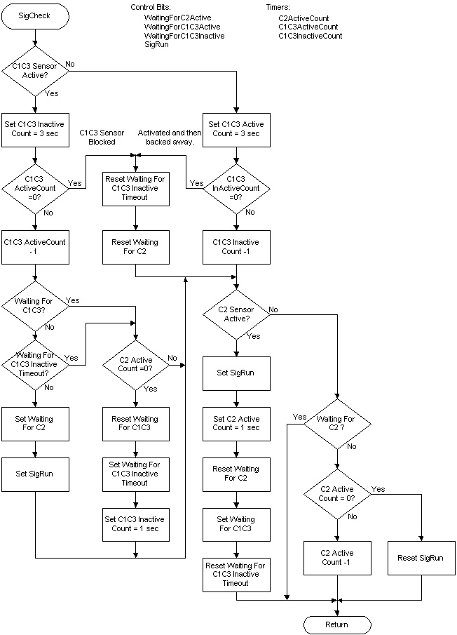
This page contains the documentation portion of the Basic Stamp 2 program that controls the grade crossings. The version 2 code improves the train detection logic and Led lamp simulation effect. The code has also been converted to PBASIC 2.5 to make the logic easier to understand. See a flow chart that details the train detection logic.
The complete code and documentation can be downloaded using this link: GradeCrossingV2.zip. The older code can be downloaded using this link: GradeCrossingV1.zip
' ======================================================================
' GradeCrossingV2.bs2                                         4-14-2005
'
' Grade Crossing Signal Control
'
' Note: This program is written using {$PBASIC 2.5} features.
'
' This program controls the signals at the grade crossings on the D&B
' model railroad. The circuit/program can support two grade crossings.
' There are two grade crossings on the layout; each with a single track.
' One of the grade crossings has gates controlled by a servo. Each grade
' crossing is composed of the following elements.
'
'                          |          |
'                          |   Road   |
'   east                C2a|          |                   west
'    ~ ====================|==========|==================== ~
'        C1                |          |C2b             C3
'                          |          |
'               Gate Servo              Sound Module
'
' Three infrared sensors are used to detect train movement. C1 and C3
' look across the track and are used to detect an approaching train.
' Sensor C2a/C2b looks diagonally across the track and road and detects
' the train as it crosses the road.
'
' Each grade crossing can include a sound effects module available from
' ICCT for singal bell and train noises. The program code switches between
' the two sounds based upon sensor input. The bell only sound is used
' when a train is detected by C1 or C3. The bell and train noise sound is
' used when a train is detected by C2.
'
' Each grade crossing can also include a crossing gate. The crossing gate
' is mechanically driven by an R/C servo which can be easily interfaced
' to the BS2 with no external components. The code varies the pulse width
' input to the servo to control its position. The final up and down postion
' of each gate and its speed are adjustable by minor changes to program
' constants.
'
' Program timing and the associated signal delays are set set by the PAUSE
' statement in the MainLoop routine. This value should be adjusted first
' if necessary to achieve the 3 second delay period; use a brief activation
' of C1 or C3 to trigger the code. Once set, the GateUp and GateDn constants
' can be adjusted if necessary for the gate positions. Finally, the GateRate
' constants can be adjusted for the desired gate speed.
'
' Hardware Description
'
' Refer to schematic sheet 5. Operationally, the design is train direction
' independent so sensors C1 and C3 can be connected to the BS2 using an
' "or" gate. This saves a BS2 I/O bit and simplifies the code. Each signal
' requires four BS2 I/O bits. Two are for the train sensors C1/C3 and C2.
' Each of the remaining two BS2 I/O bits connect to a lamp in the signals.
' All appropriate lamps from multiple signal stands at the grade crossing
' are wired in parallel. The flashing effect is created by changing the
' states of the BS2 I/O bits connected to the lamps.
'
' The BS2 I/O pins that drive the lamps are buffered using a ULN2803. This
' device can sync up to 500 milliamps of current which is adequate for
' driving most incandescent lamps. The circuit uses 6 volt lamps powered
' at 5 volts to reduce brightness for a more proto-typical appearance. A
' resistor in series with each lamp can reduce brightness further if
' necessary.
'
' An alternative lamp circuit using Led's is also shown. A single BS2 I/O
' pin can source up to 20 milliamps of current. Use care when connecting
' multiple Led's to the BS2 I/O pins. The total source current across all
' BS2 I/O pins should not exceed 40 milliamps.  The 470 ohm resistor sets
' the led current to about 1 milliamp. Adjust this resistor value to
' obtain the desired Led brightness.
'
' As used in this design, the infrared emitter/detector pairs work
' reliably for a distance up to about 6 inches using the 100 ohm emitter
' diode resistor. This distance can be improved by lowering the emitter
' diode resistor value to increase current. Do not exceed the maximum
' continuous forward current rating of the emitter diode. Some optical
' shielding may be necessary to prevent stray infrared emissions from
' affecting other detectors.
'
' BS2 I/O bit sensor inputs for an unused signal position should be tied
' to ground.
'
' An input pin of the Basic Stamp is connected to an on/off switch and
' used to enable/disable the crossing sounds. Only the crossing sounds
' (bell, passing train) are affected. All other crossing gate related
' functions (flashing lights, gates) are not affected.
'
' An input pin of the Basic Stamp is connected to another dip switch and
' used to select normal or test mode program operation. When off (1),
' normal grade crossing functions as described herein are enabled. When
' on (0), test mode is enabled. A test/exercise routine is run in test
' mode. Crossing lights are each flashed three times. The crossing gates
' are lowered and sound 1 is played if enabled. The crossing gates are
' raised and sound 2 is played if enabled. Changing the switch from test
' to normal mode causes a software reset to be performed. All internal
' working variables are set to default conditions.
'
' The normal/test mode pin is also connected to a led that serves as a
' heartbeat indicator.
'
' The ICCT sound module contains a playback IC that is programmed with
' two sounds. The sound module contains its own volume control and audio
' amplifier that can drive a speaker directly. The sound module is wired
' to the BS2 to permit program control of the sounds. The sound start
' inputs to the sound module are programmed to be level sensitive. That
' is, a sound will playback continuously as long as its start input is
' active. If building the non-ULN2803 version of the circuit, the
' polarity of the sound start bits must be changed in the code from
' active high to active low.
'
' Each gate servo is connected directly to its corresponding BS2 I/O
' pin. No special drive circuits are required unless there is a very
' long distance between the BS2 and the servo. If erratic servo oper-
' ation is noted, try a shielded twisted pair cable.
'
' Software Logic
'
' Refer to the logic flow diagram for additional detail.
'
' 1.  At program initialization, all timeout counters are set to zero.
'
' 2.  A train approaching the grade crossing is detected by sensor C1 or
' C3. This causes the signals to begin flashing and the gate to begin
' lowering. Two retriggerable timeouts are also used to detect train
' movements prior to reaching the road and being detected by sensor C2.
' If the train stops, blocking sensor C1 or C3, the signals will be shut
' off after the C1C3Active timer expires. If the train backs away, the
' signals will be stopped after the C1C3Inactive timer expires.
'
' 3.  When sensor C2 detects a train, the signals will begin flashing
' and the gates lowered if not already so. A 1 second retriggerable C2
' timeout is initiated. This timeout will again be set to 1 second for
' any C2 sensor activity during the C2 timeout period. If no further C2
' sensor activity is detected, the completion of the C2 timeout causes
' the signals to stop flashing and the gates to be raised.
'
' 4.  C2 sensor activity also initiates control logic which causes the
' outbound train C1 or C3 sensor activity to be not acted upon as an
' approaching train. When C1 or C3 detectes the outbound train, the
' retriggerable C1C3Inactive timer is set to 1 second. Once the last car
' of the outbound train passes the C1 or C3 sensor, this timer will
' expire and reset the signalling cycle.
'
' 5.  All Cx sensors are again monitored for activity which begins a new
' signaling cycle.
'
' Test Cases
'
' Case 1: A train is detected by C1 or C3 and then backs away. Operation
' 2 handles this case.
'
' Case 2: A train is detected by C1 or C3 and also C2 and then backs
' away. Operations 3 and 4 handle this case.
'
' Case 3: During the C1/C3 timeout operation 4, the train is backed up
' through the crossing. Operations 3 and 4 handle this case.
'
' Case 4: A short slow train is detected by C1 or C3 and stopped before
' C2 is reached. The C1/C3 timeout completes. If the train proceeds
' inbound, this case will be handled by operation 3. If it backs up, a
' new signaling cycle will begin when C1 or C3 is reached.
'
' Case 5: A short slow train is detected by C2 and stopped between C2
' and the outbound C1 or C3 sensor. All timeouts complete and the signals
' are stopped. If the train proceeds outbound, operation 4 handles this
' case. If the train backs up, this case is handled by operation 3.
'
' Case 6: A long train is detected by C1 or C3 and stopped before C2 is
' reached. The C1/C3 inactive timeout completes because of a gap between
' the cars does not cause C1 or C3 sensor activity. When the train
' proceeds, action depends on which sensor activates first; C1/C3 or C2.
' If C2, this case is handled by operation 3. If the C1/C3 sensor, a new
' signaling cycle will begin.
'
' Case 7: A train is detected by C1 or C3 and stopped before C2 is reached.
' The C1/C3 active timeout completes because of solid C1 or C3 sensor
' activity (train stopped). When the train proceeds, action depends on
' which sensor activates first; C1/C3 or C2. If C2, this case will be
' handled by operation 3. If C1/C3 sensor, a new signaling cycle will
' begin.
' ======================================================================
Navigation: Grade Crossing D&B Home Buczynski.com Index
Copyright © 2006 Don Buczynski
San Diego, California