Status 10-18-2020: The D&B web server software has been updated to
include a new "live" page for the yard trackage. A yard trackage diagram is displayed with the
turnout lined routes colored red. See DnB_RpiPhoto for a screen
capture image. Also corrected an issue associated with wye turnout T07. An incorrect power polarity could
occur under some conditions following manual T07 positioning. This resulted in a short circuit
and DCC track power shutdown by the Digitrax booster. The wye section power polarity relay is now
set as part of manual T07 positioning.
Status 9-15-2020: The D&B software has been updated to include a new
feature. A simple web server has been added to permit read-only viewing of operational data using an
external web browser. The associated perl code is contained in DnB_Webserver.pm and dynamically builds
the various HTML pages when requested. Minimal code additions to DnB.pl and DnB_GradeCrossing.pm
cosolidate the needed operational data to support web page generation. See
DnB_RpiPhoto for screen capture images.
Status 8-12-2020: The D&B operational software has be updated to
correct an issue whereby the TurnoutDataFile.txt file could become corrupted. This occurs when
the DnB.pl program is started manual at the CLI and the user enters Ctrl+C to terminate the
program.
New functionality was added to compensate for semaphore flag and crossing
gate mis-positioning due to layout benchwork thermal expansion. A DS18B20 temperature sensor was
added to the Rpi to permit ambient temperature input. The adjustment is computed and applied in
the MoveTurnout code. A test was also added (-w) for code validation.
Status 7-15-2020: The D&B operational software has be updated to be more
compliant with general perl coding practices. The 'use strict' pragma is now used in all modules. Some
areas of code required minor changes but all existing functionality is intact. New test functionality
(-a option) was added. When specified, code which simulates layout operations is run. Simulation based
data for sensor, turnout, and routing input is used instead of layout input. This simulates a train moving
over the layout trackage without having to run a real train.
Status 7-24-2019: The D&B operational software has successfully completed
QA testing and has been found to be in compliance with design requirements. Code release 1.0 is now
available for general use. Many thanks to the team for their hard work and dedicated effort to bring this
project to fruition.
Status 6-26-2019: The D&B operational software has been debugged and
tested and is now considered to be code complete. The various software functions behaving as expected
and trains are once again moving on the layout.
Status 4-29-2019: Completed and tested the mainboard wiring associated with train
position sensors S1 through S13. Additional test code (-n option) was added to facilitate easier sensor
testing by sounding tones when a sensor activates/deactivates.
Status 4-09-2019: Mainboard wiring has been completed for the signals, block
detectors, all keypads, and shutdown button. Circuit wiring was verified using DnB.pl command line options
to run associated tests. Shutdown button operation verified using DnB.pl operational code. During keypad
testing, code changes were required to account for keypad orientation (clock position of connector) and
schematic wiring. It was also necessary to change the code associated with the shutdown button. Using the
wiring shown in the schematic, active low (0) is presented to GPIO21 when the button is pressed.
Status 10-28-2018: The RPi perl code is test bench operational. Servos
move and signal LEDs flash colors using the DnB embedded test software. The layout interfacing hardware
is still under procurement and construction.
Language and Environment
The control software for the Raspberry Pi version of the D&B model railroad is
written in perl. This language has a large body of free downloadable support code on the internet.
A number of advanced perl programming techniques, primarily forks and child processes, are used to
implement the necessary code functionality. The perl language is included in the Raspbian OS distribution.
Use the Standard Pi OS distribution, not NOOBS.
Update your Raspberry Pi Raspbian operating system to the latest version using the
console command line.
sudo apt-get update
sudo apt-get dist-upgrade
sudo apt-get autoremove (post-upgrade replaced file cleanup)
The DnB code needs perl version 5.24.1 or later. To check the perl version installed on your RPi enter,
perl -v
The latest perl version can be installed using the console command line.
sudo apt-get install perl
'WiringPI' and the perl package 'Forks::Super' are also required. Standard
raspbian (Pi OS) includes WiringPi. The web server functionality requires 'HTTP::Daemon', 'HTTP::Status',
and 'Sys::HostAddr'. Use the following to install these modules at the RPi OS command line.
sudo cpanm Forks::Super
sudo cpanm HTTP::Daemon
sudo cpanm HTTP::Status
sudo cpanm Sys::HostAddr
For temperature input, a DS18B20 temperature sensor is used. Raspbian directly supports
its 1-wire protocol using modprobe. The device is configured as follows.
In file /boot/config.txt add:
dtoverlay=w1-gpio
In file /etc/modules add:
w1-gpio
w1-therm
Following Rpi reboot, use the command ls /sys/bus/w1/devices
to list the DS18B20's unique device ID and update the $sensor variable in the Turnout::GetTemperature
code.
The RPi hostname can be changed using the Raspbian desktop GUI. From the main menubar, select:
Preferences->Raspberry Pi Configuration.
An observational note. In some respects, the DnB perl code sharing the RPi resources
is more complex than the previous Basic Stamp version which used multiple independent CPUs. The RPi
version however, provides a far greater level of extensibility for the future needs of the model railroad.
A few interesting statistics.
| Line count comparison, Perl and Basic source code. |
| Language | Code lines | Comment lines | Test lines | Total |
| Basic | 2057 (56.1%) | 1449 (39.1%) | 152 (4.1%) | 3658 |
| Perl, D&B 1.0 | 2669 (49.1%) | 2276 (41.1%) | 498 (9.1%) | 5443 |
| Perl, D&B 1.4 | 4044 (49.1%) | 3367 (41.1%) | 678 (8.1%) | 8089 |
The D&B model railroad control program consists of the following files. All files are
collocated in a common directory. The perl BEGIN section in the main DnB.pl code adds the startup directory to
the search path (@INC) that is used to locate the supporting DnB code modules (.pm). All other perl program
dependent code module paths are defined during perl installation on the RPi.
| DnB.pl | Main program file. |
| DnB_GradeCrossing.pm | Functions related to grade crossing operation. |
| DnB_Mainline.pm | Functions related to mainline track section operation. |
| DnB_Sensor.pm | Functions related to acquisition of sensor input. |
| DnB_Signal.pm | Functions related to driving the trackside signals. |
| DnB_Turnout.pm | Functions related to driving the track turnouts. |
| DnB_Yard.pm | Functions related to setting yard turnouts. |
| DnB_Message.pm | Common functions used by all code modules. |
| DnB_Simulate.pm | Simulation data and associated code. |
| DnB_Webserver.pm | Functions related to the Webserver and HTML page generation. |
| web directory | Web page related CSS and image files. |
Change History
| Code Version | Comment |
| DnB_code_20201018.zip | • Code
release 1.5
• DnB.pl - Added call in main loop for collection of yard turnout position data.
• DnB_Yard.pm - Added subroutine for processing turnout positions and web page overlay images.
• DnB_Webserver.pm - Added code to generate yard "live" web page. Updated navigation bar to include Yard page selection.
• web directory - Added background and overlay files for yard "live" page.
• DnB_Mainline.pm - Corrected wye section T07 position power polarity issue.
|
| DnB_code_20200915.zip | • Code
release 1.4
• DnB.pl - Added code to main loop for cosolidation of web page operational data.
• DnB.pl - The -w option enables web server operation when specified on the startup CLI.
• DnB.pl - Previous -w initiated temperature testing now uses the -u option.
• DnB.pl - CLI help text updated for -u and -w options.
• DnB.pl - Added internal description for web server interface and operational data exchange.
• DnB_GradeCrossing.pm - Added code for consolidation of web page grade crossing operational data.
• DnB_Webserver.pm - New program module containing webserver related functionality.
• web directory - New directory holding static image and CSS files.
• Operators Guide - Updated for -w and -u options. Added web server section.
|
| DnB_code_20200812.zip | • Code
release 1.3
• DnB.pl - Reduced the number of our declarations.
• DnB.pl - Corrected Ctrl+C related TurnoutDataFile corruption. Data save operation move from
Ctrl_C subroutine to end of DnB.pl code. Refactored the orderly shutdown sequence.
• DnB.pl - Corrected issue where semaphore and gate servos were set to middle position during
power on.
• DnB.pl - Added -w option to CLI and help text.
• DnB.pl - Added 'Temperature' and 'Timeout' to the %TurnoutData hash.
• DnB.pl - Added console message to display temperature when the sensor module is initialized.
• Turnout.pm - Added the GetTemperature and TestServoAdjust subroutines.
• Turnout.pm - Updated MoveTurnout subroutine to apply temperature adjustment to gate and semaphore servo positions.
• Operators Guide - Updated for -w option.
|
| DnB_code_20200715.zip | • Code
release 1.2
• All perl code modules updated to include the 'use strict' pragma.
• DnB.pl - Added -a option to CLI and help text.
• DnB.pl - Changed MainRun variable to include a value for simulation mode.
• DnB.pl - Added code to main loop 'step A' to retrieve simulation mode sensor values.
• Simulate.pm - New supporting code functionality and data for simulation mode operation.
• Operators Guide - Updated for -a option.
|
| DnB_code_20190816.zip | • Code
release 1.1
• DnB.pl - Corrected a few yard routes that contained incorrect turnout positions.
• DnB.pl - Added yard routes to suport turnout positioning for thru-trains on tracks 3, 4, and 5.
• Yard.pm GetYardRoute - Added code functionality for tracks 3, 4, and 5. When both ends of one of
these tracks is specified within 5 seconds of each other, the intermediate turnouts are set for
train passthru of yard. This is most often used with track 5. It eliminates the need to enter
yard route 5/5 to close any open ladder track turnouts.
|
| DnB_code_20190724.zip | • Code
release 1.0
• DnB.pl - Corrected handling of servo driver board initialization errors.
• Turnout.pm InitTurnouts - Added code to perform a range/limit check of the TurnoutDataFile PWM values prior to use.
• Turnout.pm MoveTurnout - Corrected code. Servo move speed for rates below 50 is now working properly.
• Turnout.pm SetTurnoutPosition - Added check/correct code to prevent servo position beyond MinPos or MaxPos limit.
• Sensor.pm I2C_InitSensorDriver - Description updated to clairify GPIO bits.
• Mainline.pm ProcessWye - Corrected logic error associated with S09 that was introduced in the 20190716 code.
|
| DnB_code_20190716.zip | • Updated
the DnB.pl and Mainline.pm files.
• DnB.pl shutdown - The servo board channels are now turned off. PCA9685 placed into sleep mode.
• Mainline.pm MidwayTrack - Opposing T05/T06 turnout now set correctly for user entered input.
• Mainline.pm ProcessHoldover - Corrected invalid train wreck alarm reported for a very slow moving train.
• Mainline.pm ProcessWye - Corrected multiple T07 setting from S08 and S09 input.
|
| DnB_code_20190713.zip | • Updated
only the DnB.pl program.
• Changed default audio player volume to -1800.
• Numerous code comment corrections.
• A few more yard route corrections.
• Simplified the shutdown sequence.
|
| DnB_code_20190628.zip | • Changes
were made to the %YardRouteData table in DnB.pl. Corrected a number of routes that were based on an inaccurate
yard trackage diagram. Simplified a number of routes to support additional train movements.
|
| DnB_code_20190626.zip | • Changes
made to most of the software modules.
• Corrected code for proper power polarity relay settings.
• Corrected keypad button definitions for the manual holdover routes.
• Lengthened the midway turnout delay before the turnout is reset.
• Additional operation messages were added to the console output.
• Corrected the grade crossing logic to handle blocked sensors.
• Added code to DnB.pl to perform an orderly shutdown.
• Added description to DnB.pl for automatic startup using rc.local file.
|
| DnB_code_20190429.zip | • Updated
DnB.pl and Sensor.pm.
• Added -n option CLI processing to DnB.pl.
• Added TestSensorTones subroutine to Sensor.pm. Run when -n option is specified.
|
| DnB_code_20190409.zip | • Updated
DnB.pl, Sensor.pm, Message.pm, and Signal.pm.
• Changed code for active low (0) shutdown button functionality.
• Added test to -s option to set all signals to a specified color.
• Added test to -k option for for shutdown button.
• Changed definitions in %ButtonData hash for use with keypad wiring shown in schematics.
• Changed KeypadChildProcess %matrix for 4x4 keypad connector at 6 o'clock orientation.
|
| DnB_code_20181230.zip | • Changed
sound player to 'aplay' program for better headphone jack sound quality.
• Updated DnB.pl, Mainline.pm, Message.pm, and Yard.pm for sound player change.
• Added wave sound files for aplay program and placed in new 'wav' subdirectory.
• Added code and -v CLI option for setting sound volume using 'amixer' program.
• Removed code and configurations associated with the omxplayer program.
|
| DnB_code_20181125.zip | • Defined
holdover position sensors in DnB_main.pl %SensorBit hash.
• Added %PositionLed hash in DnB_main.pl to map holdover position sensors to panel LEDs.
• Added PositionChildProcess to DnB_Sensor.pm; reads sensors and sets cooresponding LEDs at 4 cps.
|
| DnB_code_20181110.zip | • Code changes for holdover
1x4 keypad; DnB.pl, Mainline.pm, and Sensor.pm.
• Changed CLI option used to direct console output to USB terminal; now uses -r.
• CLI options -o, -m, and -c now set the specified turnout (or all if 0) to Open, Middle, or Close respectively.
• CLI -f option does a backup of existing TurnoutData file and creates a new file with default data.
|
| DnB_code_20181105.zip | • Signal.pm test code fix,
grade crossing command, 'start' to 'start:apr'.
• DnB.pl -i option fix, sudo added to i2cdetect system call. |
| DnB_code_20181103.zip | Updated Turnout.pm to
correct servo board lockup following console ctrl+c entry. |
| DnB_code_20181028.zip | Initial code release. |
General Description
D&B Operators Guide PDF file.
The DnB.pl main program file contains a large amount of description that is not
repeated here. Please refer to this documentation for the essential details regarding how the program
operates and a clearer understanding of its code structures and design.
The DnB.pl file contains the program configuration and working data variables. A
turnout configuration file is created during program shutdown using the current positions of the turnouts.
This file is loaded during the next startup, if present, to persist the turnout positions from the previous
layout operating session. This file can also be user edited between starts to change the Open, Close, and
Rate values for each turnout. This is typically needed when turnout servos are installed or replaced on
the layout.
Data structures in the main program are referenced by pointer to the called subroutines
as needed. Subroutines use and update this data and return status code values. Forked child processes pass
data to the parent using functionality provided by the Forks::Super module. This module overloads the default
fork functions and provides a wealth of additional functionality. This module has helped to simplify the
design of the RPi based program code.
The Main Program Loop , running at about ten cycles per second, orchestrates
the overall program flow and sequence of operations. In general, it reads the sensor inputs and then calls
the various turnout, signal, and track section processing routines. Many of the called subroutines are
coded as state machines which rely on being periodically called; though not for strict timing. Essentially,
subroutines store a needed future activation time in a working variable. With each main loop call, the
subroutine compares the current time with the stored future time and performs its functions based on the
result.
The Grade Crossing code utilizes a state machine and child process. The child
process is responsible for flashing the signal lamps. The state machine logic is called once per main
program loop iteration. State data that is used for grade crossing control is persisted in the GradeCrossingData
hash. Each grade crossing is in one of the following states; idle, gateLower,
approach, road, gateRaise, or depart. The
persisted values, current sensor bit values, and state transition logic move the signal through these states.
Refer to the DnB_GradeCrossing.pm file for more details.
The Mainline code coordinates automated and user input functions
related to the Holdover, Midway, and Wye track sections. Automated functions include train presence
detection using block detectors and across-the-track infrared sensors. This input is used to position
turnout points that direct a train onto a specific track. User input via keypad button can be used to
override these turnout positioning behaviors.
The Sensor code is used to initialize the I2C GPIO extender boards and get
user keypad related input during program operation.
The Signal Color code, using block detector input, sets each signal to the
required color. A track block is 'occupied' when a power drawing locomotive or car is present.
The block protecting trackside signals have LEDs that are two lead red/green devices. Each LED is wired
to two consecutive shift register bits. Red is illuminated with one current flow direction and green is
illuminated with the opposite current flow direction. The current flow direction is determined by which of
the two register bits is set high/low. The semaphore color is set by its flag board position which is
servo actuated. Once the flag board has been moved into position, the signal lamp is illuminated.
The Turnout code provides functionality for positioning the servos that
are physically attached to the turnout points. The open/close movement is accomplished over a 0.75 second
interval using a forked process. After fork, the parent stores the PID of the child process. The operation
is in-progress until this PID is reset. The child code completes the servo movement independent of other
turnout positioning or software activities. Upon completion, the child updates the turnout position in the
parent, resets the PID, and then terminates. This is accomplished using Forks::Super stdout/stderr related
functionality.
The Yard code sets the yard turnouts based on user keypad input. Two keypad
button presses are required which specify the desired from and to tracks. If the input corresponds to a
valid yard route, the appropriate turnout points are set. A keypad indicator and audio tone confirms
button input to the operator.
The Message module contains console messaging functions, general program
support functions, and the Raspbian sound player interface function. The various beeps that are sounded
during operation were created using a tone generation feature in Audacity and saved as WAV and MP3 files.
The Simulate module contains the code and data that is used when the -a
option is specified on the DnB.pl startup CLI. The initialization function loads the simulation commands
into a working hash. The SimulationStep function is called by the main loop to get the sensor bits for
the step. The SimulationStep code also initiates any simulation specified yard routes or individual
turnout positionings. Refer to the EndToEnd routine for details.
The Webserver module contains the code that is used when the -w
option is specified on the DnB.pl startup CLI. When enabled, an external web browser can be used to
view various layout operational data. The browser connection point (IP:Port) is displayed on the console
output. The IP value is the RPi hostname or corresponding numeric address (xxx.xxx.xxx.xxx). Port is the
DnB.pl defined $ListenPort value; default 8080.
The DnB program code displays operational messages on the console or optionally
to the RPi serial port. For headless operation, all console messages can be suppressed by specifying the
-q option on the startup command line. Output of built in program debug messaging is enabled by a command
line specified debug option which includes a numeric value to control message verbosity. There are some
sections of code, primarily child processes that use the STDOUT and STDERR filehandles, where debug
code is commented out. This code can be uncommented for program debug if needed. This code will interfere
with normal program operation and should be commented out when debug is completed.
The following summarizes the startup program sequence.
1. Process these command line options, if specified, and then exit program.
• Program help (-h).
• I2C address display (-i).
• Creation of new TurnoutData file (-f).
2. Check for and terminate any DnB associated orphan child processes.
3. Open serial port (-y) for redirect of console message output.
4. Display 'DnB program start' message on the console. $MainRun variable set to 1.
5. Initialize GPIO pins and I2C devices.
• RPi GPIO pins.
• I2C I/O Plus board 1; MCP23017 chips 1 and 2 (sensor input).
• I2C I/O Plus board 2; MCP23017 chips 3 and 4 (keypad scan and button input).
6. Start child processes.
• KeypadChildProcess (16 button keypad)
• ButtonChildProcess (two 4 button keypads)
• PositionChildProcess (holdover red/yellow train position indicators)
• SignalChildProcess (Signal shift register driver)
• GcChildProcess 1
• GcChildProcess 2 (with crossing gates)
• Webserver (if -w is specified on CLI)
7. Initialize turnout servos.
• Load previous TurnoutData file if available.
• Initialize servo boards 1 and 2; PCA9685 chip.
• Set servo channels to CLI (-o|-m|-c) or TurnoutData specified PWM value.
8. Display ambient temperature in degrees C.
9. Perform command line specified testing. Test termination results in program exit.
• Sensor test (-b, -n)
• Keypad test (-k)
• Grade crossing test (-g)
• Signal test (-s)
• Turnout servo test (-t)
• Power polarity relay test (-r)
• Sound player test (-p)
10. Display 'DnB main loop start message' on the console. $MainRun variable set to 2 (simulation) or 3 (operation).
11. Run main loop until terminated by ctrl+c or shutdown button.
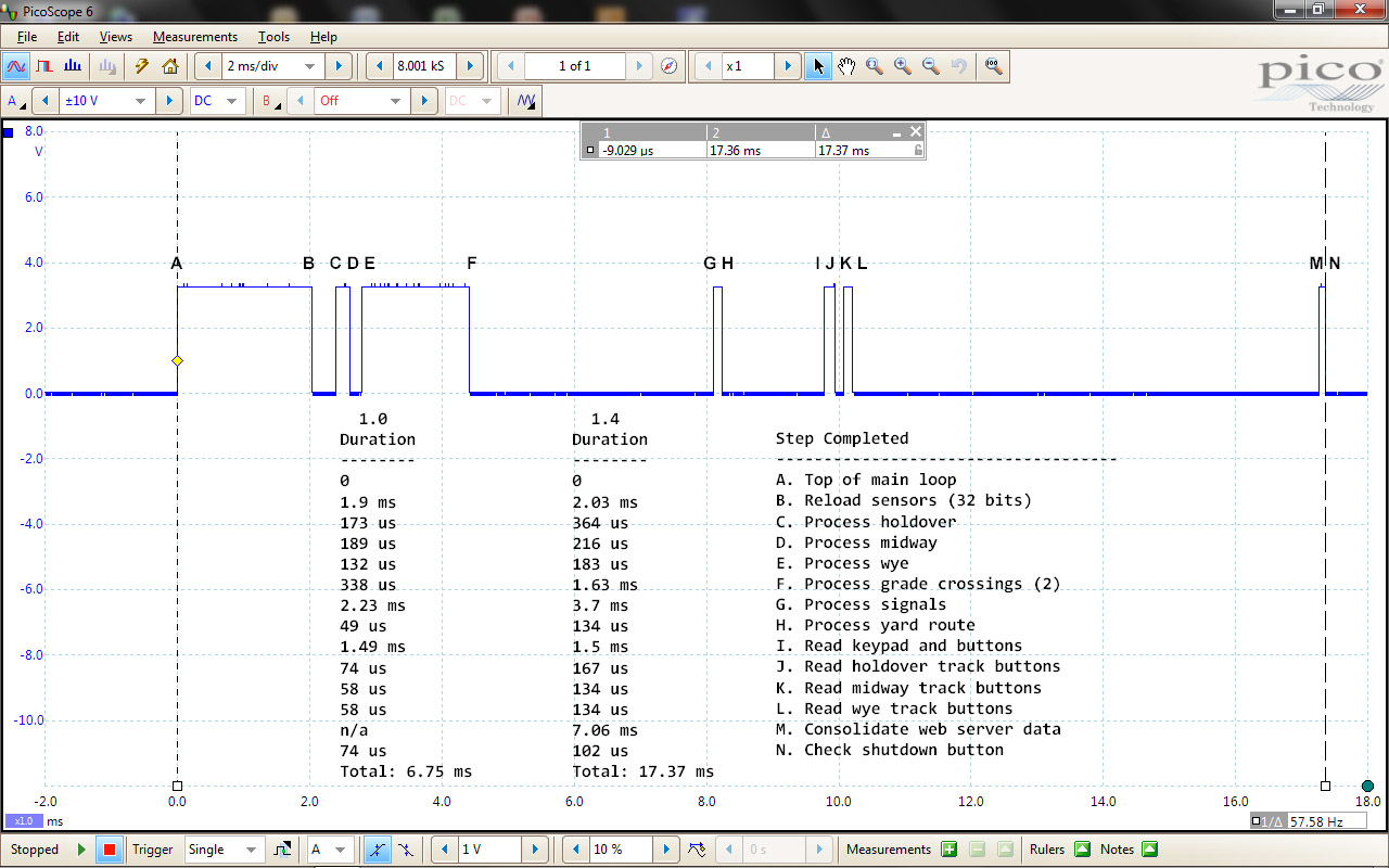
A. Top of loop. Read sensors or get simulation data (32 bits).
B. Process holdover track section sensors. Set turnouts as needed.
C. Process midway track section sensors. Set turnouts as needed.
D. Process wye track section sensors. Set turnouts as needed.
E. Process both grade crossing track sections.
F. Process signals. Set colors based on block detector inputs.
G. Set next turnout for an in-progress yard route request.
H. If no in-progress yard route, get new yard route input.
I. Process holdover track section route button input.
J. Process midway track section turnout button input.
K. Process wye track section turnout button input.
L. Consolidate and save data for web server.
M. Check shutdown button. Initiate shutdown sequence if set.
N. 90 msec loop delay.
12. User initiated program termination; ctrl+c or shutdown button.
a. Ctrl+c input: Stop child processes. Program exit.
b. Shutdown button: Continue main loop processing and -
• Sound 5 countdown tones, one each second.
• Cancel if shutdown button pressed again.
• Perform orderly shutdown of child processes, signals, relays, and indicators.
• Save turnout position data to file.
• Shutdown Raspbian OS.
Child Processes
GcChildProcess
A grade crossing child process is launched during main program startup
for each grade crossing. This child process is used to start and stop grade crossing signal lamp flash
operation. Crossing gates, if present, can't be driven by this child process due to a Forks::Super
restriction. A child process is not allowed to spawn a child process; servo movement is essentially a
child process. Gate movement servos are handled by the grade crossing state logic.
The child pid value is stored in the GradeCrossingData hash. This pid value is used by the parent state
logic to send messages to the child process. Forks::Super 'child_fh' functionality is used for communication
between the parent and child processes. The parent sends a start/stop signal message to the child's stdin.
The child process checks its STDIN file handle for new messages and acts on them accordingly. The following
messages are used.
start:apr - Start flashing lamps with bell sound 1.
start:road - Start flashing lamps with bell sound 2.
stop - Stop lamp flash and bell sound.
exit - Terminate GcChildProcess.
KeypadChildProcess
The keypad child process is launched using Forks::Super and processes user input
from a Storm 4x4 keypad.
Inside the keypad, the buttons are arranged in a 4 by 4 grid. When a button is pressed, a row and column are electrically
connected. For example, in the following diagram, pressed button [5] connects row B to column 2.
| col | | 1 | | 2 | | 3 | | 4 | |
| row | | | | | | | | | | | | | |
| A | -- | 0 | --- | 1 | --- | 2 | --- | 3 | -- |
| | | | | | | | | | | | | |
| B | -- | 4 | --- | [5] | --- | 6 | --- | 7 | -- |
| | | | | | | | | | | | | |
| C | -- | 8 | --- | 9 | --- | A | --- | B | -- |
| | | | | | | | | | | | | |
| D | -- | C | --- | D | --- | E | --- | F | -- |
| | | | | | | | | | | | | |
The keypad is connected to eight pins of a MCP23017 port. Four of these pins are configured
as output and drive the keypad columns. The other four are configured as input with pull-up and connect to the keypad
rows. By sequentially driving a single column pin low and then sequentially sampling the row pins one at a time, a
pressed button can be identified. With no button pressed, all button coordinates will read high (1) due to the
pull-up. A pressed button coordinate will read low (0). For multiple pressed buttons, the first button detected
is used.
The keypad child process scans the keypad 10 times a second. When a button press
is detected, the child process sends the button number (0-F) to its STDERR filehandle. The button press
value can then be read by the parent code using Forks::Super::read_stderr($KeypadChildPid).
ButtonChildProcess
The button child process functions in a manner similar to the keypad child process. It is
launched using Forks::Super and processes user input from the two Storm 1x4 keypads. When a button is pressed,
a column is electrically connected to common. For example, in the following diagram, pressed button [2] connects column 3
to common.
| col | | 1 | | 2 | | 3 | | 4 | |
| | | | | | | | | | | | | |
| common | -- | 0 | --- | 1 | --- | [2] | --- | 3 | -- |
| (gnd) | | | | | | | | | | | | | |
The keypad button columns are connected to a MCP23017 port. These pins are configured
as input with pull-up. The keypad common is connected to ground. With no button press, all button coordinates
will read high (1) due to the pull-up. A pressed button will read low (0). For multiple pressed buttons, the
first button detected is used.
The button child process scans the keypad 20 times a second and differentiates
between single and double button presses. A double button press is reported if the same button is
pressed within a one second time period. When a button press is detected, the child process sends
a string, s(0-3) or d(0-3), to its STDERR filehandle. The button press string can then
be read by parent code using Forks::Super::read_stderr($ButtonChildPid).
PositionChildProcess
The position child process reads the IR sensors associated with the hidden
holdover blocks B01 and B02. These IR sensors are physically located near the exit ends of these
hidden holdover tracks. When a train interrupts an IR beam, the PositionChildProcess illuminates
the corresponding panel LED. This provides a visual indication of train position within these
hidden holdover tracks. Warning point (yellow) and stop point (red) LEDs are used. In this way,
the engineer can stop the train prior to activating the S02 or S03 sensor which causes the holdover
turnouts to be set for train departure. No other data is exchanged between this child process and
the main program.
SignalChildProcess
The signal child process is launched using Forks::Super and is used to drive
the 74HC595 shift register that illuminates the trackside signals. This simplifies the code and timing
requirements needed to show yellow signals by toggling between red and green. This is accomplished by
using two 32 bit variables. In one, the signal color bits are set to red. In the other, the signal
color bits are set to green. The two variables are alternately sent to the shift register by the
SignalChildProcess. For non-yellow signal positions, the bits are set to the same color in each
variable.
Two time delays are used to balance the red and green 'on' times. This provides for a coarse adjustment
of the yellow color for all signal positions. The variable resistors on the driver board are then used
for fine yellow color adjustment of each signal.
The combined time delays further control the repetition rate of the signal child's while loop.
This rate should be just high enough to eliminate flicker when the yellow color is displayed;
about 25-30 cycles per second. The lowest possible cycle rate is desired to minimize CPU
loading by the signal child's while loop. To further minimize CPU load, the signal child optimizes
itself by checking for any yellow signal indications. When no yellow signals are being displayed,
the loop repetition rate is reduced to 4 cycles per second.
Forks::Super is used to communicate new signal settings. The new data is read and used by the signal
child process until subsequently updated. To minimize child processing, the message data is formatted
for immediate child use by the main program code.
SignalMask - 32 bit mask, all 1's. Changed signal two bits set to 0.
SignalColor1 - 32 bit mask, all 1's. Changed signal set to color value; red (0b01), green (0b10), yellow (0b01), or off (0b00).
SignalColor2 - 32 bit mask, all 1's. Changed signal set to color value; red (0b01), green (0b10), yellow (0b10), or off (0b00).
Terminator - "-\n". Used to remove processed messages from the child's stdin.
Webserver Child Process
The webserver child process is launched, when -w is specified on the DnB.pl startup CLI,
using Forks::Super. A socket access point is created at web address <RPi hostname>:$ListenPort. The
web server code then monitors the socket for browser connections. Incoming requests are passed to NewConnection()
where they are validated and file paths adjusted for physical location; $WebRootDir or $WebDataDir. The request is
then passed to RequestHandler() where the response HTML is generated and sent back to the browser. This
dynamically created HTML is stored and served from $WebDataDir; ramdisk /dev/shm. Static files are served from the
$WebRootDir directory; e.g. /home/pi/perl/web.
Cascading Style Sheets (CSS) are used for web page decoration and element placement. Two CSS files are sent to the browser.
Each is optimized for window size larger or smaller than 800 pixels. The browsers selects which CSS to use based on the
current browser window size. Transparent overlay files are used on the Live page to color the active track blocks
and signals. Java-script is used to periodically auto-refresh the track block and signal overlay files.
Test Code
A number of tests are available for use with code verification and layout operational adjustments. They are invoked
when needed using the appropriate DnB.pl command line option. Tests are run individually and do not involve the DnB
main program loop. This helps to focus testing to specific functions and features. Each test runs until terminated
by ctrl+c console input.
Sensor test (-b option)
This test reads the user specified sensor chip(s) and displays the value(s) on the console. This
continues once per second until terminated by ctrl+c. While running, each sensor bit can be manually activated to verify
the associated circuitry is working as expected. The MCP23017 chip(s) to be tested are specified using a comma separated
list or range. For example:
DnB.pl -b 1,3 Read and display chips 1 and 3.
DnB.pl -b 1:4 Read and display chips 1 through 4.
Sensor tone test (-n option)
This test reads the sensor inputs defined in the SensorBit hash twice a second. When a bit change
from inactive (0) to active (1) is detected, tones are sounded corresponding to the hash key of the active bit. For example,
SensorBit{00} sounds one tone, SensorBit{07} sounds eight tones. A double tone is sounded when the bit becomes inactive (0).
A console message is also output detailing the bit change. This facilitates sensor operability testing at remote
layout locations; such as manually blocking the infrared emitter to detector light path. This test runs until terminated
by ctrl+c.
Keypad test (-k option)
This test reads the stderr messages generated by KeypadChildProcess and ButtonChildProcess
and displays the results on the console. Reads are performed at a two second interval until terminated by ctrl+c.
For the 4x4 keypad, the 1st entry LED is toggled between on and off with each button press. For the 1x4 keypad,
single and double press buttons are reported.
DnB.pl -k Read and display keypad inputs.
Grade crossing test (-g option)
This test bypasses the grade crossing sensors and sends the 'start:apr',
'start:road', and 'stop' commands directly to the grade crossing child process. The gate
servos are positioned if present on the grade crossing. The sound effects circuits are also
activated.
DnB.pl -g 1 Test grade crossing 1.
DnB.pl -g 1,2 Test grade crossings 1 and 2.
Signal test (-s option)
This test exercises the functions associated with the block protection signal and runs until
terminated by ctrl+c. The signals to be tested are specified using a comma separated list or range. For example:
DnB.pl -s 1,5 Cycle signals 1 and 5; red, green, yellow, and off.
DnB.pl -s 1:12 Cycle all signals; red, green, yellow, and off.
Prefacing the range with a r causes random signal selection and color setting.
DnB.pl -s r4:9. Random signal 4 through 9; set random color red, green, yellow, or off.
Prefacing the sequential or random range with a g causes the grade crossing signals to be
included in the test run. Grade crossing 1 and 2 are started for color green and yellow respectively.
Grade crossing 1 and 2 are stopped for color off and red respectively. Crossing gates are not positioned.
DnB.pl -s g1:12 Cycle all signals; red, green, yellow, and off. Include grade crossings.
Turnout servo test (-t option)
This test exercises the functions associated with the turnout servos and runs until terminated.
The servos to be tested are specified using a comma separated list or range. For example:
DnB.pl -t 1,3,5 Exercise servos 1, 3, and 5; sequential positions Open, Middle, Close.
DnB.pl -t 1:10 Exercise servos 1 through 10; sequential positions Open, Middle, Close.
Prefacing the range with a r causes random servo selection and Open/Close positioning.
DnB.pl -t r1:10. Exercise servos 1 through 10; random order, positions Open and Close.
In the above commands, about 10 servo position changes are performed per second. This verifies the functionality
of multiple concurrent servo moves. This rate exceeds the maximum expected number of concurrent position
changes (the longest yard route is 8 turnouts) during normal layout operation. The console output shows the inprogress
operations. This can also be viewed in a separate command console using the linux top command. The number of
DnB.pl processes shown, minus 1 for the test code, is the concurrent inprogress operations. The CPU utilization can
also be seen in the top command output.
Prefacing the sequential or random range with a w causes the positioning to be done one servo at a time. This verifies
the child/Forks::Super pid reset functionality.
DnB.pl -t w1,3,5 Exercise servos 1, 3, and 5; wait for each operation to complete before next.
DnB.pl -t wr1:10 Exercise servos 1 through 10; wait for each operations to complete before next.
Demo clips on YouTube:
Sequential 1:32
Random 1:32
Set servo position (-o x, -m x, -c x)
These commands set the specified servo number x to its open, middle, or closed position as defined in
the TurnoutDataFile.txt file. Used for servo mechanical and turnout point rail adjustments. The program exits once the
position is set. When x is specified as 0, all servos are set to the specified position. For example:
DnB.pl -m 0 Set all servos to the middle position.
DnB.pl -c 1 Set servo 1 to its closed position.
Sound player test (-p option)
This test is used to verify the linux sound player configurations and audition the available sound
files. The available sound files in the D&B sound file directory are listed along with an associated number. When a number
is entered by the user, the corresponding sound file is played. Entry of sound number zero (0) terminates the test.
DnB.pl -p
Demo clip on YouTube:
Audio Player Test
Power polarity relay test (-r option)
This test is used to verify the power polarity relay operation. The relays are sequentially
energized for 5 seconds and then de-energized for 5 seconds. This test runs until it is terminated with ctrl+c.
DnB.pl -r
Servo temperature adjust test (-u option)
This test is used to verify the servo position temperature calculation. Input parameters
specify a servo number (gate or semaphore) and one or more temperatures in degrees C. The first temperature is
set and the servo is positioned. The cycle repeats for each specified temperature. Each position (Open, Middle,
Close) is tested unless a single position is specified; o, m, or c. For example, to test the semaphore flag
board positioning (servo #30) 'Close' position, the following command would be used.
DnB.pl -w 30c:30,25,20,15
A low tone is sounded at the start of each position. A high tone sounds for each
temperature change at that position. Changes occur at 2 second intervals. This test runs until terminated
by Ctrl+C.
Simulation mode (-a option)
This test simulates train movements and turnout operations on the layout. The default
EndToEnd simulation runs until terminated by ctrl+c. Sensor bits, yard routes, and turnout positions
that are stored in the %SimulationData hash are used instead of the actual layout input. In this mode, the
operational code is exercised without actually running a train on the layout. Refer to the %SimulationData
hash for details. Use debug level 0 to display additional simulation data on the console.
DnB.pl -a
Raspbian OS Startup and Shutdown
The following Raspbian OS configuration changes are used for startup and shutdown of
the RPi. Search the web for other alternatives.
DnB.pl Program Start
The /etc/rc.local file is used to automatically launch DnB.pl once the Raspbian OS has
completed boot. Configure rc.local using the CLI as follows.
1. Edit the file: sudo nano /etc/rc.local
2. Add the following to the file just before the exit 0 line. Change the path to the DnB.pl file if stored
in a different location.
/home/pi/perl/DnB.pl -w -q
3. Use the editor commands ^O and ^X
to save the file and exit the editor.
Alternatively, the line ' >> /dev/shm/DnB.log 2>&1 '
(without quotes) could be used in place of the -q to send the DnB.pl console output to a log file. The
log file could then be monitored using tail -f /dev/shm/DnB.log in
a seperate command window. Use a path in /home/pi if the log
needs to be retained when the RPi is powered down.
During Raspbian OS boot and automatic DnB.pl launch, if the shutdown button is held down,
the DnB.pl program will acknowledge the button hold and then exit. No DnB child processes will be started. The
RPi will then be usable for normal Raspbian CLI/GUI interaction using monitor, mouse, and keyboard. Use the
CLI/GUI from this point to shutdown Raspbian.
DnB.pl Program Shutdown
The shutdown button is monitored by the DnB.pl program. Detection of a button press
initiates a 10 second countdown during which five tones will be sounded. At the end of the delay, the main
program performs an orderly shutdown of the software processes and places the hardware interfaces into a
safe condition. During the countdown, shutdown can be aborted by another press of the shutdown button.
Safe condition serves to help protect the servos, sound modules, and signal lamps should
layout power remain on for an extended period. The following shutdown steps are performed.
1. Stop all child processes.
2. Raise crossing gates and semaphore flag board.
3. Wait for in-progress turnout moves to complete.
4. Turn off all servo channels.
5. Turn off all signal lamps.
6. Turn off all GPIO driven relays and indicator lamps.
7. Turn off holdover indicator lamps.
8. Save the current servo positions to TurnoutDataFile.txt.
9. Shutdown Raspbian OS using: sudo shutdown -h now
Once the Raspberry Pi green activity LED is no longer flashing, about 10-15 seconds, it is safe to power off
the layout electronics.
DnB.pl Mainloop Timing
The following shows the timing of the main processing loop when the -z option is
used to enable toggle of the GPIO20_TEST pin. Each bit toggle delimits a section of the main loop code
to aid in code analysis and tuning.
Timing for the 1.0 and 1.4 code versions are shown. The additional demands on the
RPi CPU in the 1.4 code version has impacted the main loop iteration rate. The grade crossing and
sensor/turnout data consolidations have added the most time; about 8.3 milliseconds. But these data
consolidations are only performed every 10th iteration and no noticeable impact to overall
responsiveness is observed.
The main loop code includes a static time delay (not shown) to set the iteration period
to about 10 cycles per second. This helps to ensure timely operation of Raspbian and the child processes. Tests
using higher iteration rates consumed more CPU resources while having minimal/no benefit to overall operation.
Analysis of the 1.4 code version using the Raspbian CLI top command indicates a 20% to 23% CPU
utilization for the combined D&B related processes.
RPi microSD Memory Card Backup
Use the following procedure to create a backup image of the RPi microSD memory
card. The backup image will contain all required software including the bootable and configured Raspbian
OS, the D&B software, and the required perl modules. The utility program Win32DiskImager is used.
1. Install the Win32DiskImager program on a computer with a USB port.
2. With RPi power off, slide out the RPi microSD card. Note that the microSD card gold fingers
are oriented on the top left side.
3. Insert the microSD card into a USB adapter and then insert the adapter into the computer USB port.
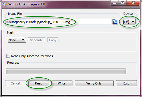
4. Launch the Win32DiskImager program.
5. Specify the folder and filename to hold the backup image.
6. Specify the USB disk device holding the microSD card to be imaged.
7. Click the Read button to copy the microSD card contents to the specified image file.
RPi microSD Memory Card Restore
Use the following procedure to restore the RPi microSD memory card or create
a new RPi microSD card from a previously created backup image. Upon completion, the microSD card will
contain all required software including a bootable and configured Raspbian OS, the D&B software, and
perl modules.
1. Insert a 32GB microSD card into a USB adapter and then insert the adapter into the computer
USB port.
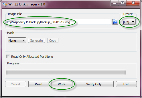
2. Launch the Win32DiskImager program.
3. Specify the folder and filename holding the previously created backup image.
4. Specify the USB disk device holding the microSD card to be imaged.
5. Click the Write button to copy the image file contents to the microSD card. If warning messages
are displayed, it is possible that the new microSD card has memory location defects that make it
unsuitable for use with the Raspbian OS. Try a different microSD card.
6. With RPi power off, orient the microSD card with the gold fingers on the top left side. Then
carefully slide the microSD card into the RPi card holder.
 Planning and Construction:
Design Goals
Track Plan
Photos
Scenery Base
Planning and Construction:
Design Goals
Track Plan
Photos
Scenery Base
Photos and Video clips:
Photo 1
Photo 2
Photo 3
Photo 4
Photo 5
Photo 6
Video Clips
Ride The D&B
Raspberry Pi Control Electronics:
Overview
Program Code
Schematics
Photos
Navigation:
D&B Home
Copyright © 2018-2020 Don Buczynski
San Diego, California