|
Block Signals |
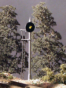
The D&B model railroad models CTC block signals for the mainline portions of the track. Single lamp three color searchlight and semaphore signals are modeled. The signals have four states; red, green, yellow, and off. When reduced to its simplest form, the track plan consists of the following blocks and signals.
Electrically isolated blocks are indicated above by a section of track identified by Bx. Each of these sections is connected to block occupancy detector. Blocks B1 and B2 are used by the mainline control BS2 circuit for hidden train hold over. Blocks B9 and B10 are the two yard bypass tracks. Blocks B3 through B8 are the primary blocks used for signaling of the mainline track in both directions. Searchlight signals are identified by Lx and the pointer indicates the train direction controlled (or lamp reflector if you want to think of it that way). The following rules are used to illuminate the signals.
Signal Color Condition Off Unoccupied block not being approached Green Approaching an unoccupied block Red Approaching an occupied block Yellow Approaching an unoccupied block; subsequent block is occupied The mainline is a single track on the D&B model railroad and trains travel in both directions. Since there is no direction information available in the current design, the control logic always sets the signals for both directions of travel. The careful observer may notice a green indication in the opposite direction of a block being vacated by a train. In the opposite direction, this is the block being approached and since it is empty, the green indication is correct. Proto-typically, this signal would probably be off. The green indication will change to off once the train moves another block forward on the mainline.
The following truth table was used when developing the signal color control logic. The table is easier to visualize using color markers and the above track diagram.
X = Active Block (Bx)
Lamp Color (Lxx) R = red, G = green, Y = yellow
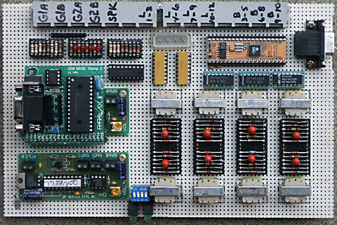
1-2 3 4 5 6 7 8 9-10 L1 L2 L3 L4 L5 L6 L7 L8 L9 L10 L11 L12 X G Y X R R G Y G Y X Y G R R G Y X Y G R R G Y X Y G Y G R R G Y G Y X Y G R R X Y G R R X Y G Y G X X R R G Y G Y X X R R R R G Y G Y X X Y G R R Y G R R G Y G Y X X Y G Y G R R R R G Y X X Y G R R Y G X X X R R G Y R R G Y X X X R R Y Y R R R R G Y G Y X X X Y G Y G R R R R G Y R R X X X Y G Y G R R G Y R R X X X X R R R R Y Y R R G Y G Y X X X X R R Y Y R R R R R R G Y X X X X Y G Y G R R R R R R G Y X X X X X R R R R Y Y R R G Y R R The block signal design uses the Parallax 40 pin Basic Stamp 2p. The BS2p40 was selected due to the number of available I/O pins it provides as well as the faster "turbo" instruction execution rate. The instruction execution rate is important since the program code will be toggling the I/O bits to produce a yellow signal color from bi-color LEDs. A flicker free yellow color is desired.
Each searchlight signal is equipped with a bi-color (red and green) LED. One power polarity causes the LED to illuminate red and the other power polarity causes it to illuminate green. Yellow illumination is created by rapidly switching between red and green. The shade of yellow obtained when switching the LED is controlled by the percentage of red and green 'on' time. Two program constants are available to fine tune the red and green 'on' duration times; equal values result in 50% on time for each color. The two constants combine to affect the overall yellow toggle repetition rate so each value should be kept as small as possible to minimize yellow color flicker. Some experimentation with the values may be required to achieve the desired shade of yellow for the LED type used.
When selecting the bi-color led, refer to the spec sheet and choose one that has similar red and green intensities. A red or green that is brighter will be difficult to balance into a good shade of yellow. Select a led with an opaque lens instead of a clear one. The red and green colors blend better with the opaque lens. The LED used in the development of the code was included in a signal kit produced by Oregon Rail Supply. The LED's are available on their website order page.
LED's with differing red/green intensities can be used but additional series diodes will be needed. General purpose silicon diodes (1N914, 1N4148) drop .6 volt. Adding two or more diodes in series with the brighter color will lower the voltage applied to that color. One diode for the other color will be necessary to provide a current path. Some bi-color led's used on the D&B model railroad required five diodes in series with the red color and one diode in series with the green color to achieve a good yellow color. Alternately, two diodes and a variable resistor can also be used. The resistor is adjusted to lower the level of the brighter color. See the hardware schematic for more details.
The signal at L8 is a moveable arm semaphore. It has an incandescent lamp and uses a R/C servo to position the signal arm/color. One of the two BS2 I/O control bits associated with this signal is connected to the servo input. The BS2 PULSOUT command is used to position the servo which moves the semaphore arm via a mechanical link. The other I/O control bit is used to drive the signal lamp.
See the hardware schematic, BS2 code description, and BS2 program code for additional details. The picture below shows the circuit board. The board holds the grade crossing circuits on the left and the block signal circuits on the right. The block signal circuits include the two yellow resistor packs and all parts down and to the right. Most of the space is occupied by eight of the ten block detectors.
For those readers who desire a non Basic Stamp design for model railroad block signalling, the following link contains many useful ideas: Model Railroad & Misc. Electronics.
Planning and Construction: Design Goals Track Plan Photos Scenery Base
Basic Stamp Control Electronics: Main line Yard Grade Crossing Block Signal Turntable
Circuit Description: Main line Yard Grade Crossing Block Signal Block Detector Turntable Power Supply Schematics
Photos and Video clips: Photo 1 Photo 2 Photo 3 Photo 4 Photo 5 Photo 6 Video Clips Ride The D&B
Propeller Control Electronics: Overview Flow Charts Program Code Schematics Photos
Navigation: D&B Home Buczynski.com Index
Copyright © 2006 Don Buczynski
San Diego, California