The reverse loop at each end of the main line presents some electrical and operational challenges. Operationally, using DC cab control, this would have resulted in a lot of power control switch flipping. Not my idea of operational fun. This lead to the investigation of Digital Cab Control (DCC) for controlling the layout. Search 'DCC basics' and 'reverse loop control' for more details on this subject. Reverse loops are easy to operate and can even be completely automated with readily available DCC components.
The hidden holdover tracks do add some complication; especially since they are not visible! I wanted a way to minimize the possibility of putting a second train onto an occupied hidden track. Crunch! I also wanted to control the entry to each holdover track. My limited experience suggests that derailments occur less often if the straight leg of a turnout is used when entering from the end with the points.
The mid point siding is another area where some automatic operation was desired. I have observed on the prototype railroads that in certain situations, turnouts that are "spring" loaded to a particular position are used. This moves the trains onto specific tracks when approaching the turnout from the point side. When approaching the turnout from the frog side, the points are pushed open by the train as it passes out of the turnout. In testing this for model trains, the use of springs for positioning the turnout points didn't work well; lots of derailments. I also wanted normal turnout positioning control to support special operational movements.
Then there is the power polarity for the upper reverse loop. Research from books and message forums indicated that the power polarity control should include all track within the reverse loop; which means the yard and industrial spurs in this track plan. The desire was to automatically change the power polarity as required by trains as they pass through the wye since this would be the only point that would cause short circuit problems. There was also the desire for a yard switcher to be independently operating and shuffling cars. A power polarity change must not affect its independent operations.
The nice thing about DCC is that there is no effect on DCC equipped locomotives when the track polarity is switched. DCC does support control of DC analog locomotives. But, a DC analog locomotive will change its direction of motion on a power polarity change. To do automatic reverse loop power control as desired, all of the locomotives operating within the reverse loops must be DCC equipped.
That's a lot of requirements and operational desires. In the effort to do all of this in some reliable way, a custom control system using the Parallax OEM Basic Stamp 2 was created. The control system handles all of the main line power polarity switching, holdover track assignment and mid point siding turnouts. The engineer of the train simply "drives".
The OEM BS2 is a small circuit board that includes the micro controller chip, EEPROM memory, and a computer interface port. The kit version of the OEM BS2 is quick and easy to assemble and well documented. The program to be run by the micro controller chip is written on a PC in a 'Basic-like' computer language. The Basic Stamp software is easy to install and use. User documentation and application examples are available online in PDF format. Once written, the executable code is transferred to the BS2 EEPROM memory where it is stored and run. The executable code is not lost when the power is removed from the BS2. It will begin running once power is again applied to the BS2.
Some serious consideration was given to the use of the Digitrax PM42 or other automatic reverse loop power controller for the reverse loops. The BS2 performs train detection and positional control of the reverse loop turnouts and as such, knows when power polarity reversals are required. Adding a couple of IC's, relays and a few lines of code is the most cost effective way to handle the reverse loop power polarity.
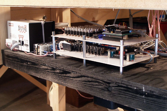
With a handful of parts (ok, maybe two handfuls) and a trusty wire wrap tool, the following circuit assembly was constructed.
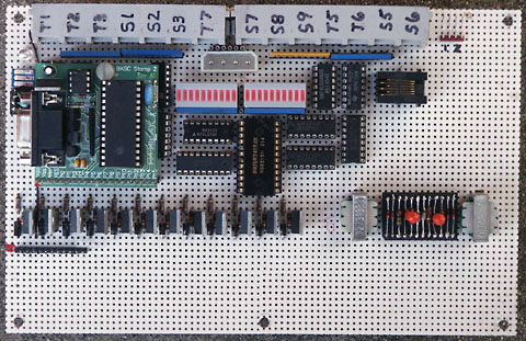
The two transformers and 24 pin header in the lower right portion of the board are the track block occupancy detector circuits. The discrete components below the BS2 module and IC's are the turnout driver circuits. The BS2 module is socket connected so it can be easily removed for programming. Note that the 20 pin right angle strip header that comes with the BS2 OEM kit was replaced with a straight one.
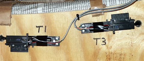
A six conductor cable was used for wiring to each turnout. Three conductors are used for the Atlas under table switch machine and three conductors for the turnout position sensor.
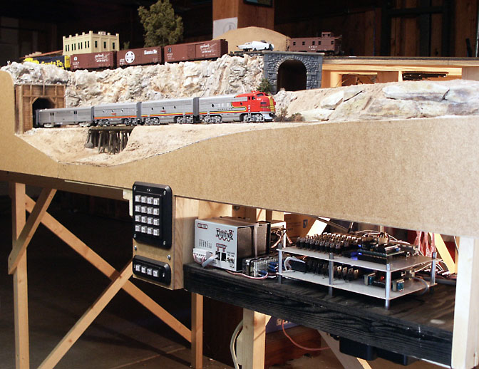
In the next picture, the mainline control board is topped by the yard route control board and connected to the layout.
Some additional indicators and parts were included in the prototype to aide in troubleshooting. The circuit was also revised a time or two after letting the smoke out of some Atlas switch machines! It is working very well now and a single train can travel through both reverse loops and the entire main line unattended. See the main line hardware schematic, BS2 code description, and BS2 program code for additional details.