When converting the software functions from multiple Basic Stamps to a single Propeller chip, a flow charting process was used. This exercise identified all of the unique functions used in each Basic Stamp and helped to better organize and plan the Propeller software. The flow charts provide a general understanding and logic flow of the various software components.
For the most part, the Propeller "Spin" language is used for the necessary software functions. In those areas where timing and performance is important, Propeller assembly language is used. An interprocess communication structure (ICS), located in main Propeller memory, is used by the software processes to transfer information between cogs.
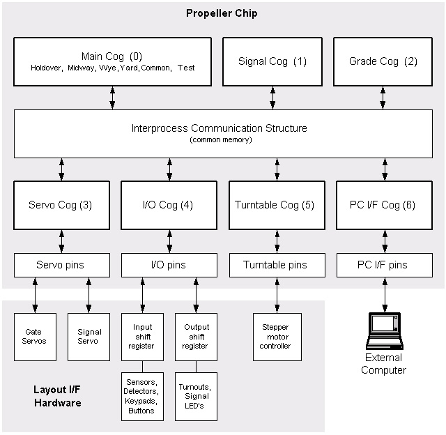
In general, I/O functions are handled by dedicated cogs that drive the Propeller I/O pins. The data values (turnout number, sensor input, signal color, etc.) are read and written to/from the ICS. The other cogs perform higher level control functions, based upon the sensor input in the ICS, and set appropriate output control values in the ICS.
Use the following links for additional flow chart details.
Main Cog:
Logic Flow
Holdover Object
Midway Object
Wye Object
Yard Object
Common Object
Test Object: 1 of 2
2 of 2
Block Signal Cog: 1 of 3
2 of 3
3 of 3
Grade Crossing Cog: 1 of 3
2 of 3
3 of 3
I/O Cog: 1 of 3
2 of 3
3 of 3
ICS Memory
Navigation: D&B Home
Copyright © 2006 Don Buczynski
San Diego, California