The interfacing hardware has significantly changed with the move from Basic Stamps to the Raspberry Pi. The overarching goal was to minimize changes to the layout wiring. This wiring connects to the control electronics using 6 pin cable connectors. These connectors plug into a new motherboard which in turn, has connections to the various RPi hat boards.
Use the following links to view each PDF schematic sheet. Downloaded
all schematic sheets in a single zip file. RpiSchematicsJpg
RpiSchematicsPdf
JPG -
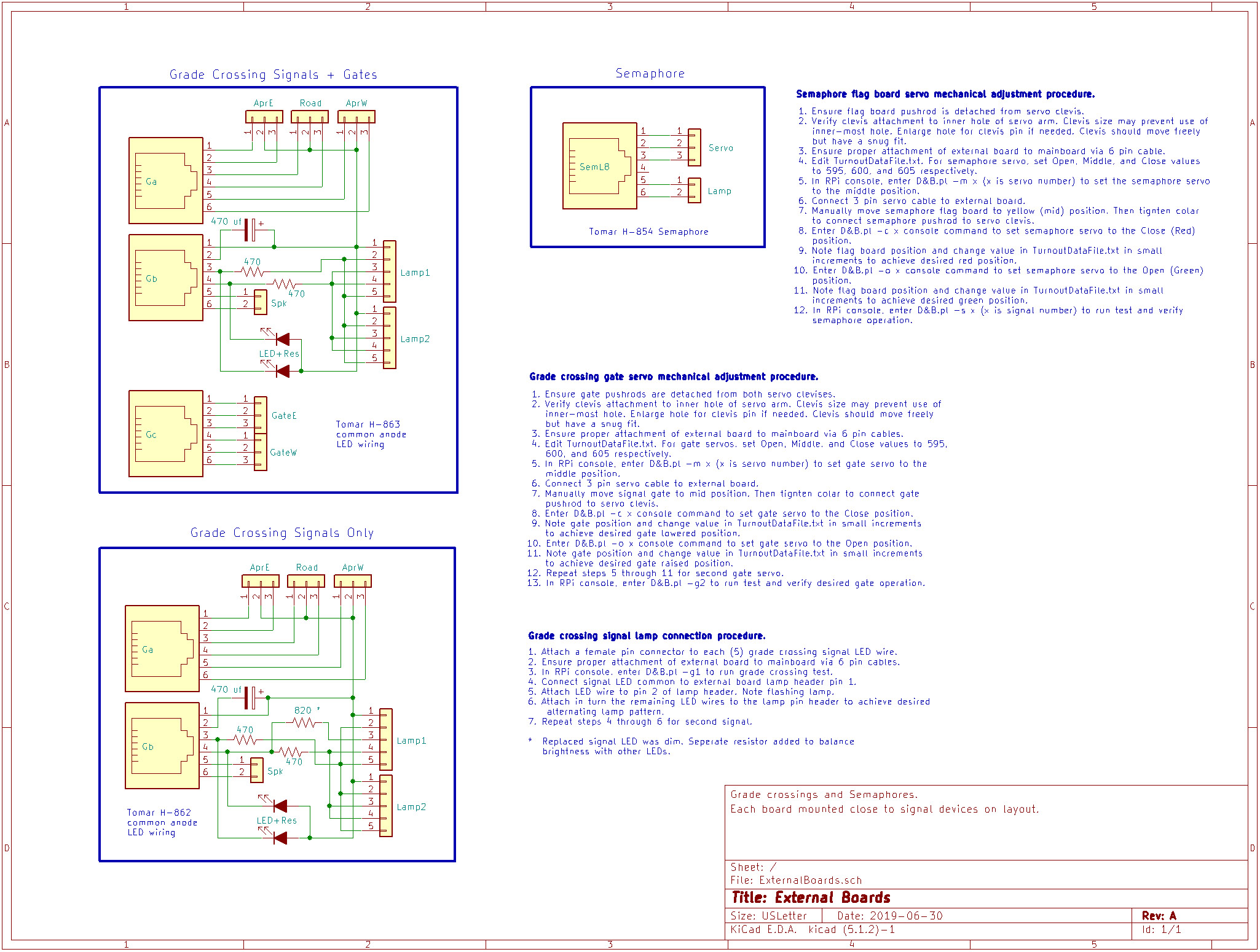
PDF - External Board Interconnect Circuits
JPG -
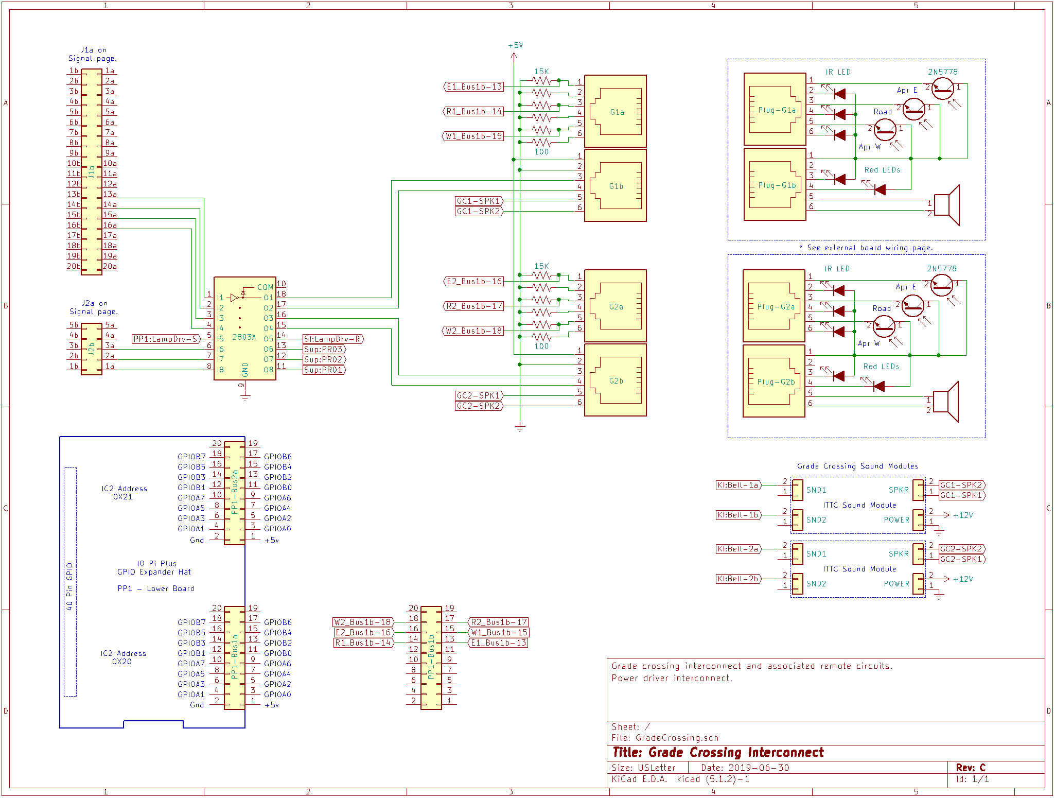
PDF - Grade Crossing Interconnect Circuits
JPG -
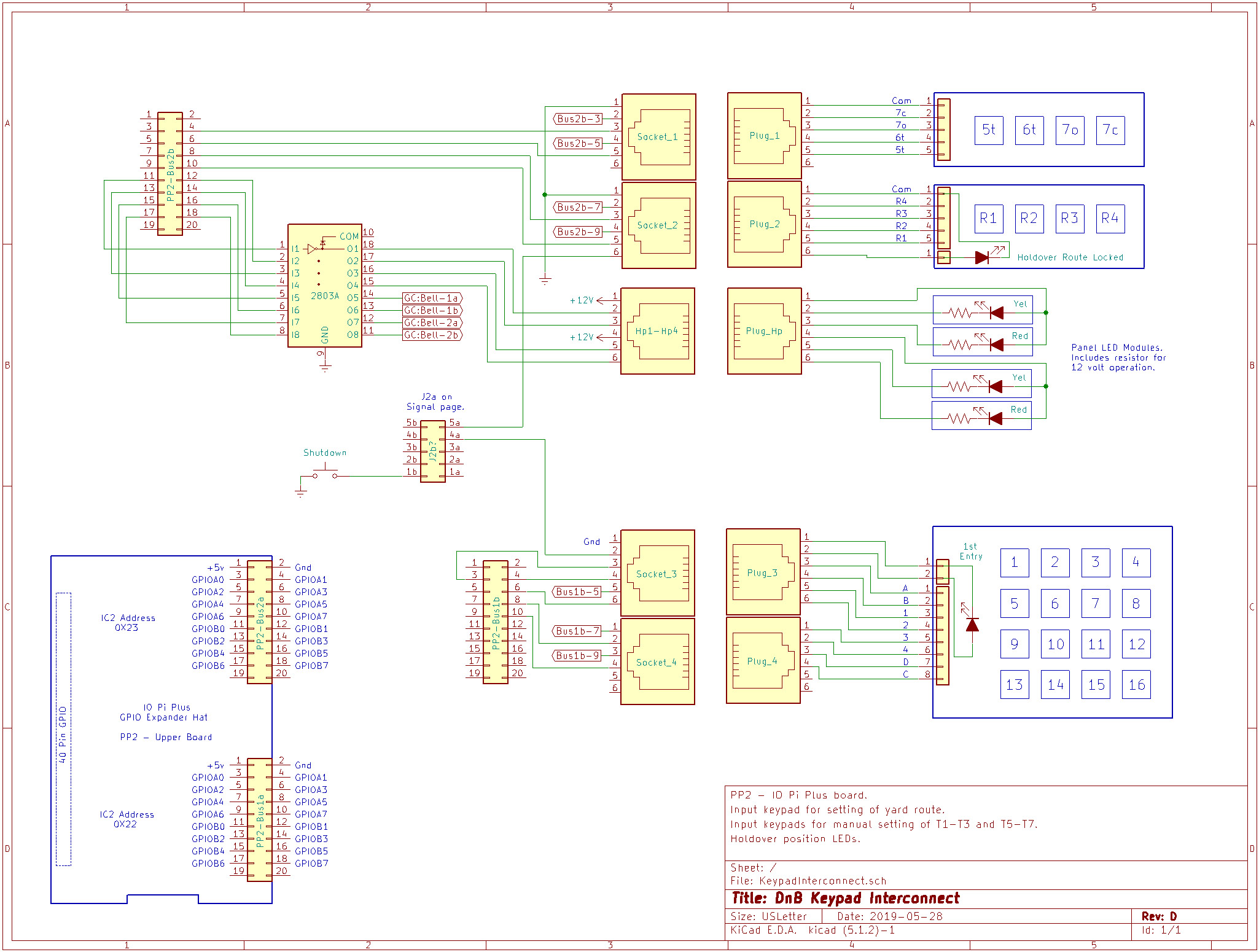
PDF - Keypad Interconnect Circuits
JPG -
PDF - Mainboard Component Placement
JPG -
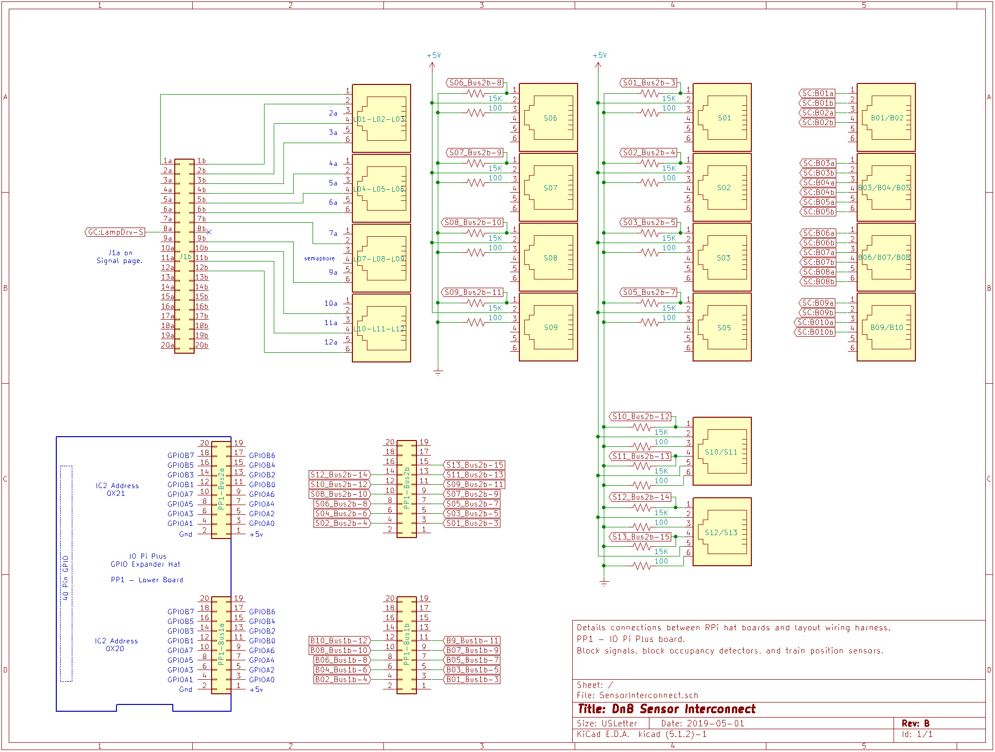
PDF - Sensor Interconnect Circuits
JPG -
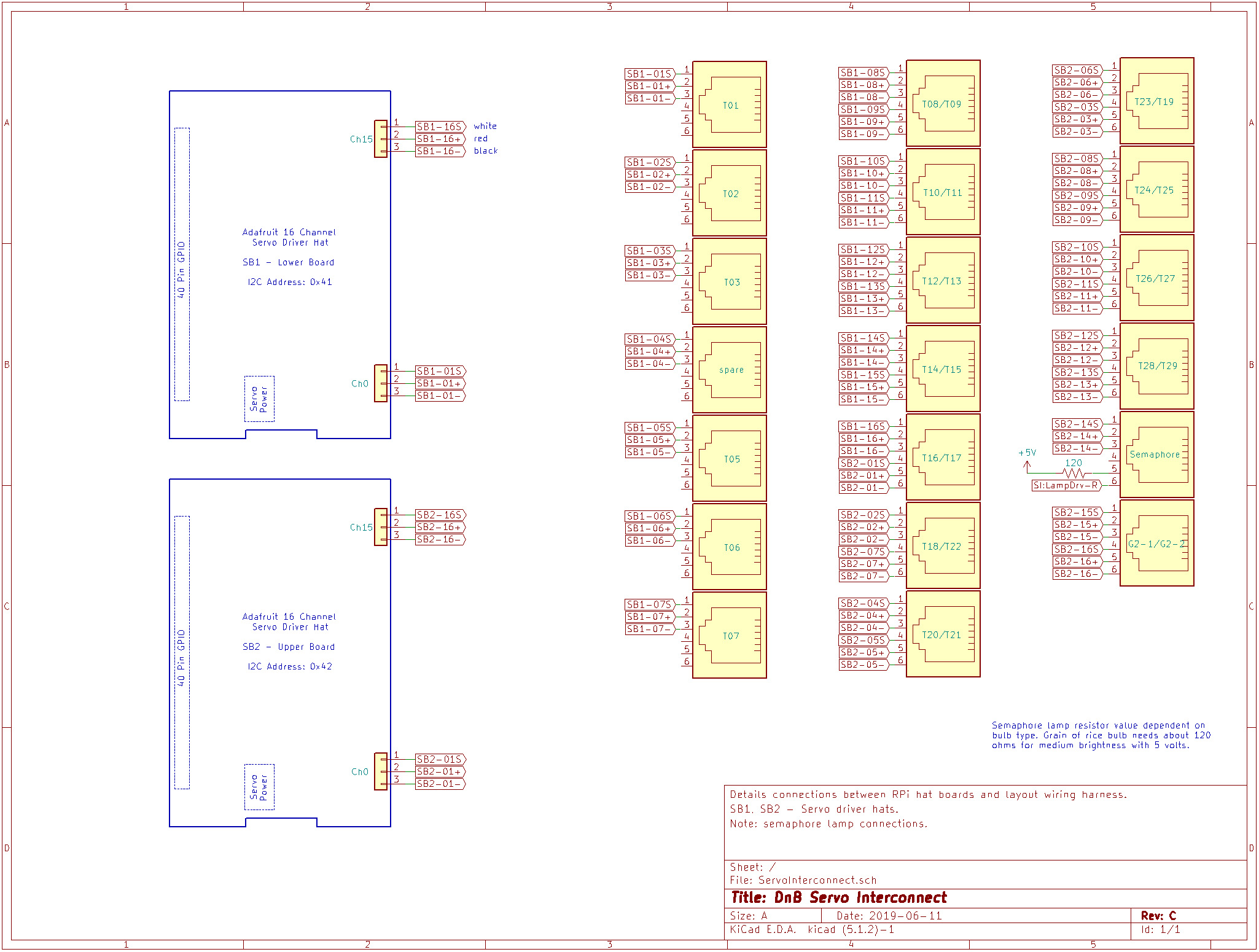
PDF - Servo Interconnect Circuits
JPG -
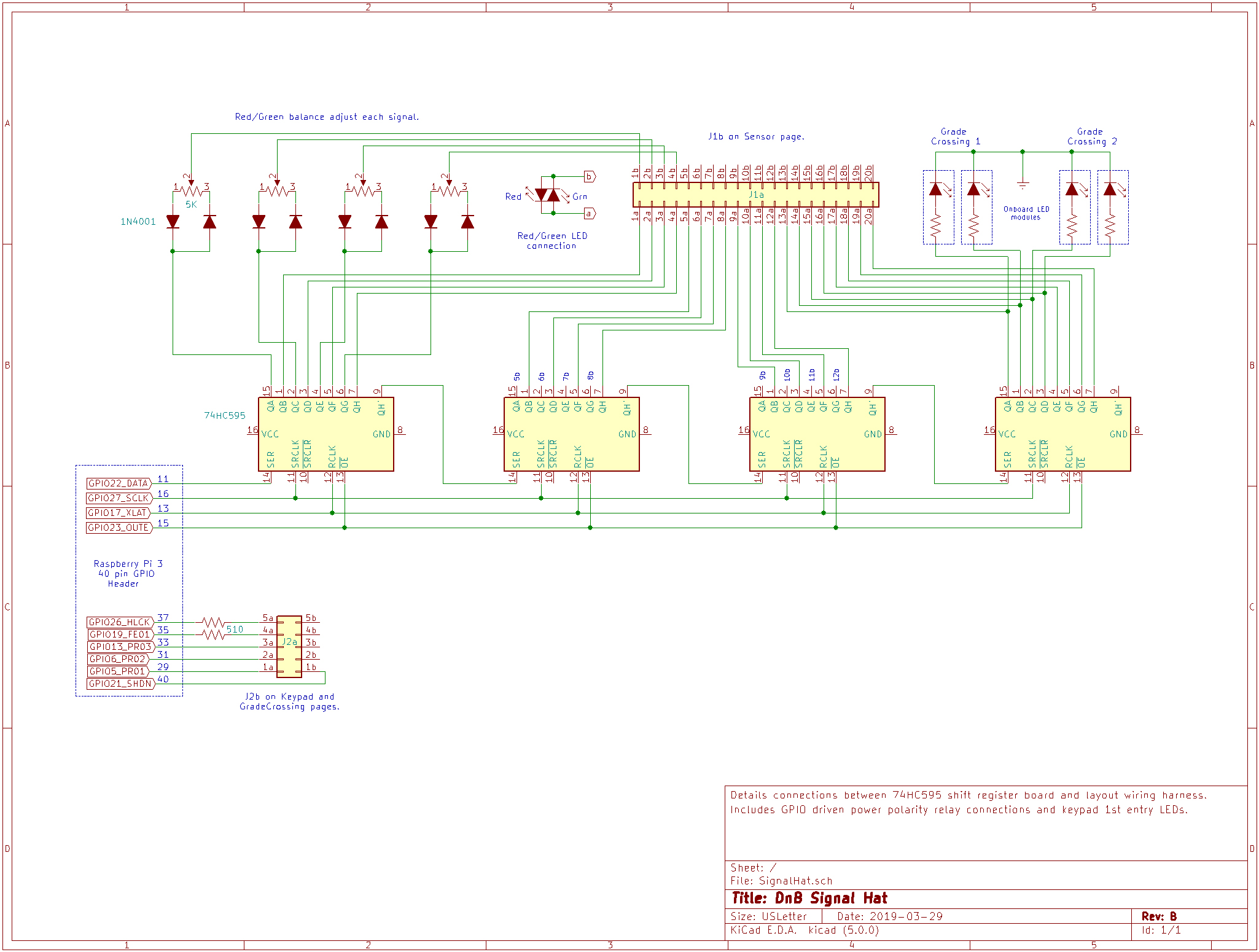
PDF - 74HC595 Shift Register Signal Circuits
JPG -
PDF - Support Circuits
Servo Driver Hat
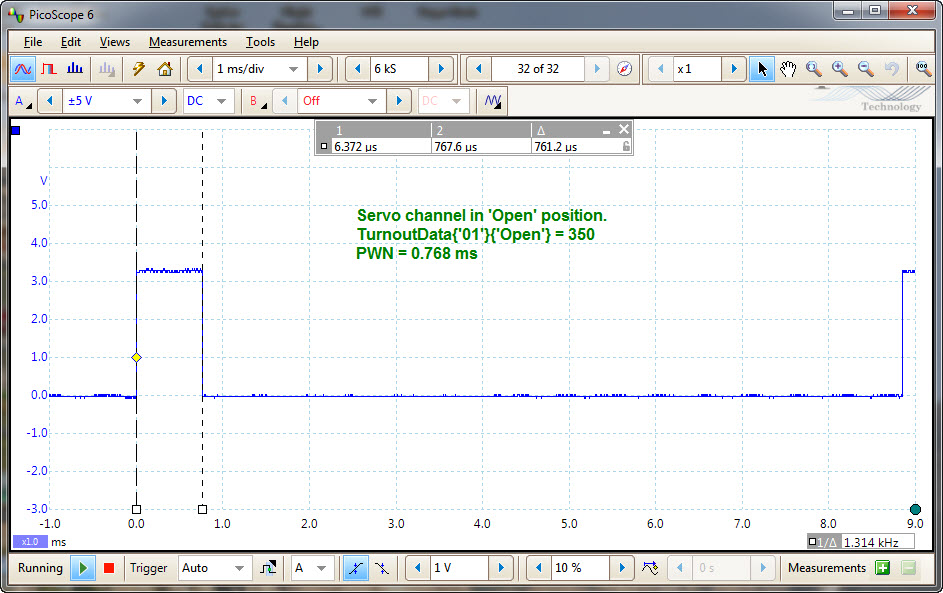
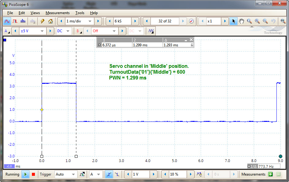
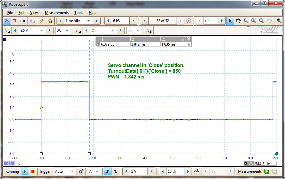
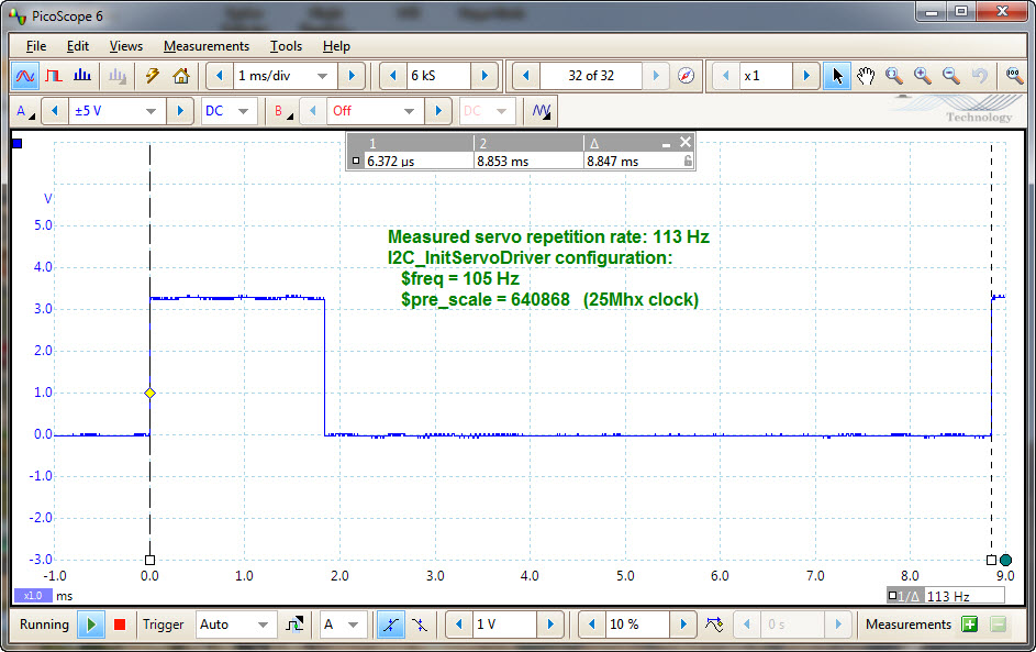
Two 16 Channel Servo Driver hats are used to drive the turnout servos. This hat uses the PCA9685 chip which is configured for operation with the SG90 R/C servo by the I2C_InitServoDriver code. Refer to the code and the PCA9685 Document for more information.
The following images show the servo PWM signal. Measurements were taken with the scope probe attached to the signal pin of first servo channel.
Click image to enlarge.
The layout uses thirty-two SG90 servos that require five volt power. Each servo driver board has an isolated power connector that is feed from a dedicated 5 volt 1.2 amp power source. The RPi supplies 3.3 volt power to the hat electronics via the 40 pin GPIO connector.
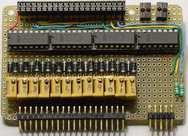
74HC595 Shift Register Circuit
A suitable commercial product for driving the track signals using shift register functionality could not be located. I briefly considered using tri-color LEDs and a 16 channel PWM board. In the end, minimum disturbance to the layout and signals won out. Therefore, a breadboard hat was constructed using four 74HC595 shift registers and point-to-point wiring. This also provided a convenient place to locate the variable resistors used to adjust the yellow color purity. Not as pretty, but functional none-the-less.
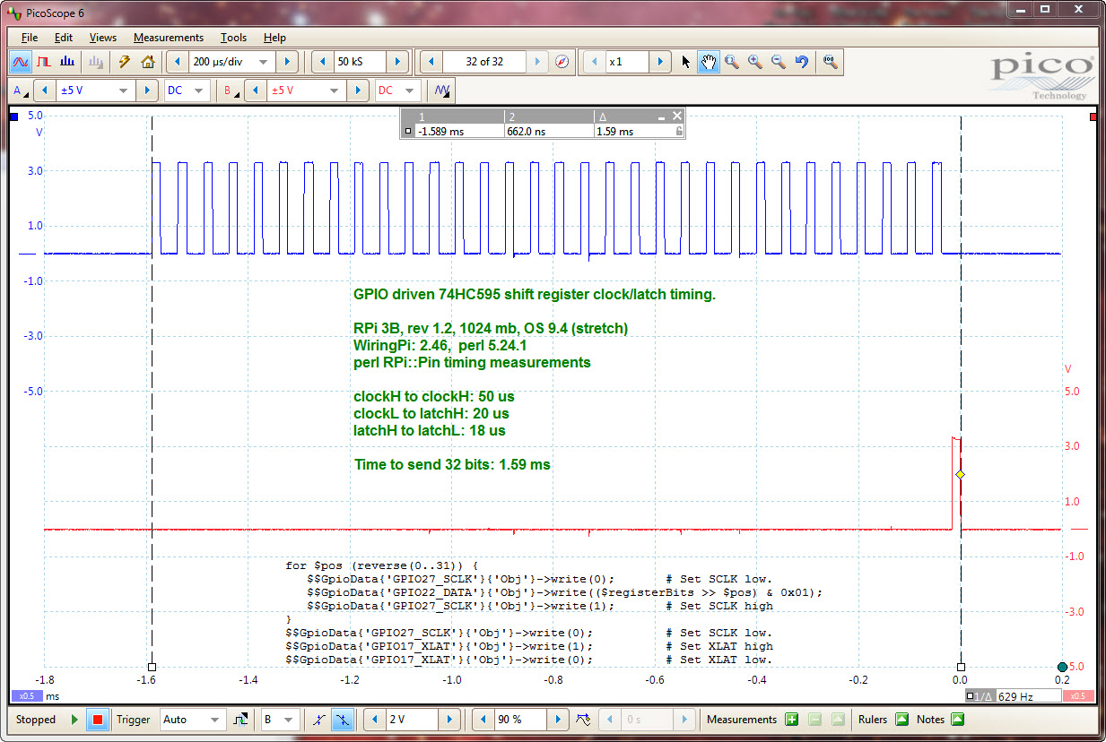
74HC595 shift register timing measurement. Scope probe A: GPIO27_SCLK, Scope probe B: GPIO17_XLAT.
DCC Block Detectors
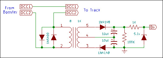
DCC power to the track is an AC signal of 10 to 16 volts. It consists of binary information encoded into the AC "carrier" by varying the width of the positive and negative peaks of the wave. This block detector design utilizes only the AC property of the signal; the binary information is not decoded. The circuit has limited drive current capacity and should be connected to high impedance input devices such as logic gates or op amps.
Each block of track to be detected must be electrically isolated by appropriate gaps in the rails of the track. Two back-to-back 1N5400 diodes are connected in series with one leg of the DCC power to a block of track. Silicon diodes typically drop about 6 tenths of a volt. Whenever a locomotive or car draws power from the track within the block, this low AC voltage will be present across the diodes. The 1N5400 diodes have a 3 amp current rating and should be adequate for HO and N scale multiple locomotive trains. Higher current diodes should be used for larger scales. More on current and short circuit protection below.
The secondary 8 ohm winding of the audio transformer is connected across the 1N5400 diodes. The voltage across the diodes is stepped up to a useable level by the primary winding of the transformer. The actual voltage present in the primary transformer winding depends on the total current being drawn within the block.
The remaining components of the circuit are connected to form a voltage doubling power supply. The 1N4148 diodes and transformer center tap provide half-wave rectification of the transformer primary voltage. Each capacitor is charged to the primary voltage on alternate half cycles. The voltage across both capacitors is double the primary transformer voltage.
The capacitor values and load resistor effect the response time of the block detector. The larger the capacitors, the further into the block the train will be before its presence is reported. The capacitors also minimize signal transients as the train enters or leaves the block as well as transients causes by dirty track and wheels. The 100K ohm resistor serves to discharge the capacitors once the block is vacated. The value determines the length of the discharge period. This value should be large enough to minimize signal transients.
The 1000 ohm resistor and 5.1 volt zener diode form a voltage divider and are included for protection of the inputs to the logic circuits connected to the detector. These components ensure that the detector output voltage does not rise above the zener diode voltage rating. Without these components, a large current draw or short circuit within the block will cause the output voltage of the detector to rise well above normal logic levels possibly damaging the attached input circuits.
The following table summarizes the detector DC output voltage under various loads. The voltage was measured across the two capacitors with the zener diode disconnected. The output voltage depends on train speed, locomotive load and power draw, and car lighting within the block.
Load Description Measured Voltage Stopped Measured Voltage Moving 10,000 ohm resistor across the track 1.3 Car with two 10,000 ohm resistor wheels (5,000 effective) 2.75 Single HO scale P2000 GP30 locomotive 3.20 5.65 Two HO scale Bachmann Spectrum series F7 locomotives 4.75 6.10 Single HO scale Athearn Genesis USRA 4-6-2 Light 3.75 5.90 All four locomotives in same block 6.00 The input voltage necessary to reliably register as a "high" condition varies. For example, the "74LS" family requires about 2 volts. The "74HC" family requires about 3.25 volts. For unpowered railroad cars, typically the last car or caboose, resistor wheels can be installed to continue producing a current in the block after the locomotives have exit. Select a value to produce the needed voltage using multiple wheel sets if required.
Short Circuits and Total Block Current: DCC power boosters are capable of delivering more than the 3 amp current rating of the 1N5400 diode. Overload circuits in the DCC power booster will normally shut down track power in a short circuit condition and protect the diodes. Short term spikes above the maximum diode current limit can probably be tolerated. Long term operation at or above maximum current levels will cause diode heating and eventual failure. If a large number of locomotives under heavy load conditions are expected to be simultaneously operated in a block, measurement of the total current draw under worst case conditions should be made. Diodes with appropriate current ratings can then be substituted, or additional diodes wired in parallel, to increase current capacity.
Photos and Video clips: Photo 1 Photo 2 Photo 3 Photo 4 Photo 5 Photo 6 Video Clips Ride The D&B
Raspberry Pi Control Electronics: Overview Program Code Schematics Photos
Navigation: D&B Home
Copyright © 2018 Don Buczynski
San Diego, California