The yard and industrial spur tracks involve a number of turnouts. During the planning stage, some thought was given as to how to simplify the setting of yard routes that involved multiple turnouts. It was not operationally appealing to me to have to match individual turnout position controls to a desired route. A Digital Cab Control (DCC) solution was investigated since many DCC systems support some form turnout control and route programming. It became apparent that the number of possible yard and spur routes would be challenging to remember and manage.
Some form of a from/to track routing scheme seemed easiest from an operational viewpoint. The engineer would enter the number of the track currently occupied followed by the number of the desired destination track. The appropriate turnouts would then be set as required to accomplish the movement. From this thinking came the addition of a second control system based on the Parallax OEM Basic Stamp 2 (BS2) module.
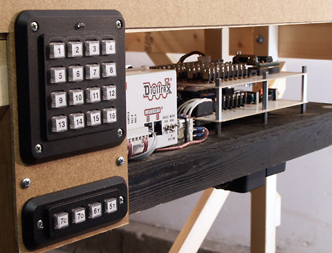
The idea involves the use of a 16 button key pad and indicator. Each yard track and industrial spur is assigned a number which corresponds to one of the key pad buttons. To set a route, the user presses two buttons in sequence. The first button pressed represents the 'From' track number and is typically the track currently occupied by the locomotive. An indicator is illuminated to show that the first track number has been entered. The second button pressed represents the 'To' track number - the desired destination track. Once two buttons have been pressed, the appropriate turnouts are opened or closed to set the route. The necessary turnout position information for each valid route is stored within the Basic Stamp program. A warning tone is sounded if an invalid route is specified.
While the BS2 has functions for interfacing to keypads, this circuit design uses individual keypad controller IC chips. This makes the circuit and coding simpler from a multi-user perspective and more modular for debug and troubleshooting. The design supports the addition of keypads in the future with minimal impact on existing code and interface hardware.
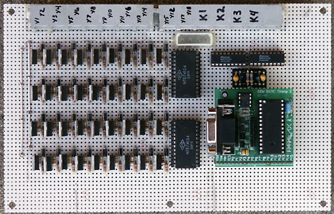
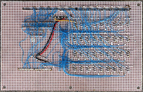
Basic point to point wiring was used due to the relatively low clocking frequencies involved.
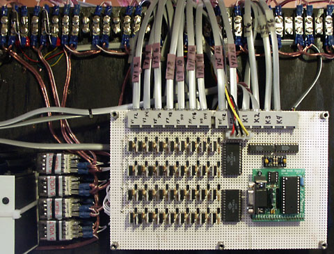
Six conductor cabling was used to wire a pair of switch machines and make it easy to remove the circuit boards if necessary. A socket was added for the BS2 module so it can be easily removed for programming. Note that the 20 pin right angle strip header that comes with the BS2 OEM kit was replaced with a straight one.
The smoke hassen't been let out of the yard Atlas switch machines yet; lessons well learned from the main line construction effort. Yard route control is working very well and is beginning to suggest other operational ideas. See the yard route control hardware schematic, BS2 code description, and BS2 program code for additional details.