The grade crossing signals on the D&B model railroad include elements for train detection, flashing light signals, sound and crossing gates. A control system based on the Parallax OEM Basic Stamp 2 (BS2) module is used to provide the necessary control functions and operational logic.
Sound for the grade crossings is provided by a custom sound
module from ITTC Sound Modules.
A custom sound module that was created for this project is called
"DonBell" and can be ordered from ITTC. The sound module is programmed with two
sounds; a crossing bell only sound and a crossing bell with background train sound. The bell
only sound is used when a train is approaching the grade crossing. Once the grade crossing
is reached, the bell and background train sound is used. When the train is no longer at the
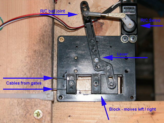
grade crossing, the bell only sound is again used. For the raising and lowering of the crossing gates, a R/C servo is
used. These servos are inexpensive and are easily interfaced to the BS2 with three wires
(two of which are power and ground). No external logic circuits are required. The servo
position is under the control of the BS2 and is changed by varying the pulse width of the
input signal to the servo. Minor modifications to a few program constants provides for the
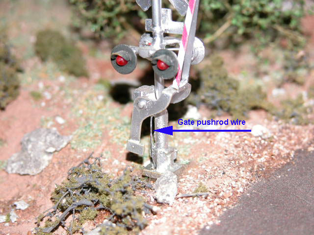
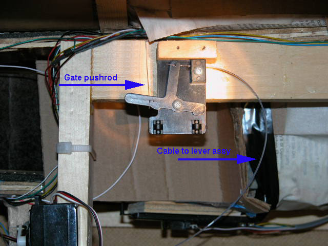
very precise control of gate speed and position. The mechanical connection of the servo
output arm to the crossing gates uses a Tomar actuating mechanism and pushrods. It is
included with the purchase of the signals and makes adjusting the total gate movement very
easy. See the hardware
schematic, BS2 code description, and
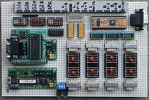
BS2 program code for additional details. The picture
below shows the circuit board. The board holds the grade crossing circuits on the left
and the block signal circuits on the right. The grade crossing circuits include the
components to the left and down from the two yellow resistor packs. The top center
header holds the resistors for the signal Led's. The four red Led's on this header are
not shown on the schematic and were added to facilitate development; two for each grade
crossing. They are wired in parallel with the signal located Led's. The sound module for
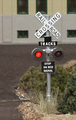
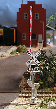
one of the grade crossings was mounted under the BS2 to conserve space. Close up pictures of the grade crossing signals. Tomar Industries signals were
used for the grade crossing signals. See the "More Photos" link at the left
for more pictures.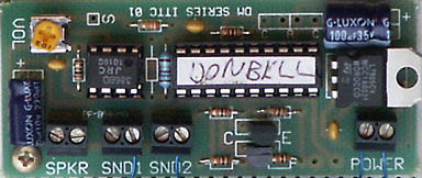
|
|
The following are video clips of the grade crossings in action. Depending on the network connection speed, better playback will be obtained if you save the complete clip to your computer before viewing. To save, right click on a link and select the "Save Target As" item.
| Video clip 1: MP4 or MPG | Video clip 2: MP4 or MPG |