|
Turntable |
This page details the turntable portion of the D&B model railroad. The following links lead to pages with additional details: Control Circuit Schematic, Code Description, and Code Listing.
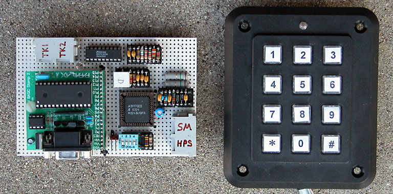
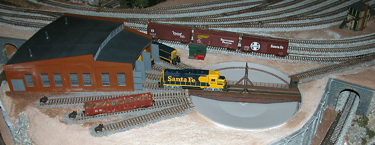
The turntable used for this project is the Walthers Cornerstone Series (R) 90' turntable, part number 933-3171. A maximum of ten track positions for both ends of the bridge track are supported; twenty total. The rotating bridge track is positioned using a stepper motor based upon user input via a keypad. See Keypad Commands for descriptions and examples. A track number and bridge end are entered using a 12 button telephone style keypad. This causes the turntable bridge to rotate and align to the associated track. Track positions are initially stored into the program using the keypad. This provides for completely arbitrary approach and service track positions.
The design provides for a wide selection of stepper motor and turntable bridge gear ratios. For example, a 12 to 1 stepper motor gear to turntable bridge gear ratio results in a step circle of about 4,800 steps. This results from using a 3.6 degree stepper motor (100 steps per revolution) that is 4x micro-stepped (400 steps per revolution). With this number of total steps in the circle, a single step is about one quarter the width of a HO scale rail. Other combinations of gear ratios and micro-step settings can be used for higher accuracy up to a maximum of 65,535 steps in the circle (16 bit word). Higher ratios may introduce more gear backlash that must be taken into account. Some planning and compromise that involves desired rotation speed, position accuracy, and gear backlash is necessary.
No program changes are necessary if other gear ratios are used. The total steps in the circle are computed and stored by the program in response to the programming mode '0' key. The bridge home position sensor is used in determining the circle size. Once the circle size is determined, all turntable bridge movements are performed based upon the total steps in the circle and the home position reference.
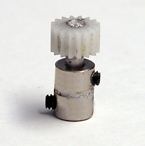
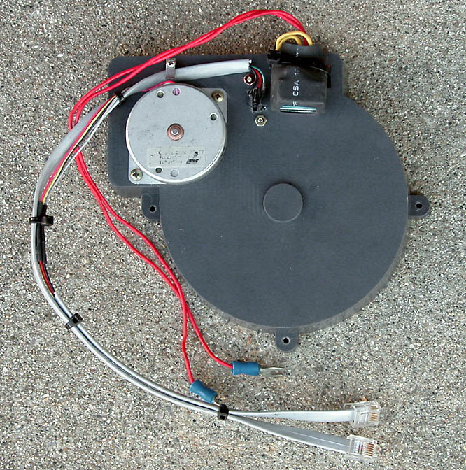
The D&B model railroad prototype turntable uses the final gear from the Walthers turntable drive motor assembly. This yields about a 12 to 1 ratio when driving the bridge gear in the Walthers Cornerstone Series (R) 90' turntable. The drive gear was drilled and epoxied to a short length of alluminum rod. Two model airplane wheel collars were soldered together and used to joint the gear to the stepper motor shaft.
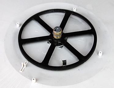
The flag for the bridge home position sensor is attached to the large bridge gear. The sensor is mounted on the inside of the drive housing such that the flag interrupts the light beam. Some careful measurements and trial fitting is necessary and best accomplished before the bridge is built. The sensor must be precisely positioned and firmly bolted to the housing base with the sensor leads passing through holes in the base. Slightly elongated sensor mounting holes in the housing base will help in positioning the sensor.
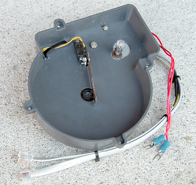
The bridge power wipers must be repositioned so as not to interfere with the home position sensor flag. The plastic piece that the wipers are attached to can be trimmed to clear the bridge gear spokes and attached to the home position sensor with epoxy. The wipers will need to be shortened a bit also. There is some flexing of the wipers which is why the sensor should be bolted to the base. The wires from the wipers exit through the original wiper mounting slot.
The stepper motor is mounted to the housing with one of the mounting bolt holes slightly elongated to permit gear mesh adjustment. After the motor is mounted, the drive gear is adjusted to the proper height on the stepper motor shaft.
Turntable Bridge Track Power
The turntable bridge track must be powered by a polarity reversing circuit. An auto reverser module is used to control the power polarity of the turntable bridge track. All service tracks are wired to the same power polarity as the lead track. These tracks are all connected to the "non-switched" MRC-AR Auto Reverser output. The turntable bridge track is connected to the MRC-AR Auto Reverser "switched" output. The power reversing module can be mounted to the housing base with the switched wires attached to the wipers.
When ready to join the housing to the main turntable base, the wipers must be flexed to be on the proper side of the bridge commutator. Referencing the above picture, the wipers are flexed to the left side of the main bearing toward the slot in the housing base. This can be accomplished with a length of string looped around the wipers and brought out through the slot in the housing base. The string holds the wipers flexed out of the way until the housing is joined to the turntable base. Releasing tension on the string and carefully removing it allows the wipers to properly contact the commutator.
Turntable Construction
Use care when constructing the turntable to ensure that the bridge rotates freely. Trim the extra spruce from the bogie wheels completely so there are no high spots. It is important that they roll smoothly when they are attached to the ends of the bridge. During final assemble, a small amount of plastic compatible greese should be applied to the main bearings, bridge gear and drive gear to reduce friction. This helps ensure that the gear backlash is consistent throughout the full circle of bridge movement.
Turntable Video Clips
The following are video clips showing the turntable in action. For slower network connections, better playback will be obtained if you save the complete clip to your computer before viewing. To save, right click on a link and select the "Save Target As" item.
Video Clip 1 Video Clip 2 MP4 or MPG MP4 or MPG
Turntable Design Updates (5-03-2005)
A number of design related issues with the turntable were identified during operational use over an extended period of time. Updates to the original design have been implemented to address the issues and are detailed as follows.
The D&B model railroad is located in a garage that is not temperature controlled. It was found that the turntable pinion and crown gear mesh varied due to winter/summer temperature changes. This resulted in a varing amount of gear backlash. Also, when the gear mesh became too tight due to expansion, the stepper motor would sometimes slip sync at certain points on the turntable rotation circle due to a slightly out of round turntable crown gear.
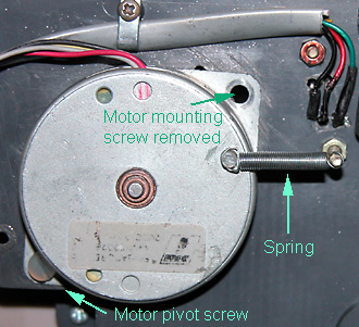
In the original design, the stepper motor was firmly mounted with two screws to the turntable gear housing. In the updated design, only one mounting screw is used and tightened only slightly so that the motor can pivot. A small spring is incorporated to provide tension to mesh the pinion and crown gears. Very little spring tension is required. This change eliminates almost all of the gear backlash when compared to the original design. The motor can now reposition itself due to temperature variations or an out of round crown gear. The result is a much smoother operating turntable.
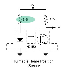
It was also found that the bridge track positioning would sometimes vary from power cycle to power cycle. Investigation and testing revealed that the home position sensor LED was being over driven. The 1k ohm current limiting resistor was changed to a 6.8k ohm resistor. The lower LED light intensity results in a consistent and repeatable home position.
Version 2 of the turntable code adds some additional documentation detail in the program listing. It also changes the micro-stepping to 8x for better position accuracy and less jitter during bridge track rotation. Some of the timing variables were adjusted to make the bridge track rotate at an appropriate rate using 8x micro-stepping.
Planning and Construction: Design Goals Track Plan Photos Scenery Base
Basic Stamp Control Electronics: Main line Yard Grade Crossing Block Signal Turntable
Circuit Description: Main line Yard Grade Crossing Block Signal Block Detector Turntable Power Supply Schematics
Photos and Video clips: Photo 1 Photo 2 Photo 3 Photo 4 Photo 5 Photo 6 Video Clips Ride The D&B
Propeller Control Electronics: Overview Flow Charts Program Code Schematics Photos
Raspberry Pi Control Electronics: Overview Program Code Schematics Photos
Navigation: D&B Home Buczynski.com Index
Copyright © 2012 Don Buczynski
San Diego, California